dc68 03172b 03 user manual

Welcome! This DC68-03172B-03 user manual is your guide to a Samsung appliance‚ offering safety‚ features‚ and usage for optimal performance and longevity.

Overview of the User Manual

This comprehensive DC68-03172B-03 user manual serves as your primary resource for maximizing the potential of your Samsung washing machine. It’s meticulously designed to guide you through every aspect of ownership‚ from initial setup and daily operation to essential maintenance procedures and troubleshooting common issues.

Within these pages‚ you’ll discover detailed instructions on safe installation practices‚ ensuring both your well-being and the longevity of the appliance. We emphasize crucial safety precautions to prevent potential hazards like electric shock‚ fire‚ or personal injury. The manual clearly outlines proper usage guidelines‚ guaranteeing safe and efficient operation of all features.

Furthermore‚ this manual provides a thorough explanation of the washing machine’s components‚ including the vital terminal block and its role in electrical connectivity. It’s structured to be easily navigable‚ offering clear explanations and practical advice for maintaining peak performance and addressing any challenges you may encounter;

Important Safety Instructions

Safety is paramount! Before operating your DC68-03172B-03 washing machine‚ carefully review these crucial safety instructions. To mitigate the risk of electric shock‚ always ensure the appliance is properly grounded and never operate it with a damaged power cord. Avoid using extension cords or adapters.

Never attempt to repair the washing machine yourself; contact qualified service personnel for any maintenance or repairs. Keep children and pets away from the appliance during operation. Do not insert hands into the washing machine while it’s running.

To prevent fire hazards‚ do not wash items that have been soaked in flammable liquids. Always disconnect the power supply before cleaning or performing any maintenance. This manual stresses adherence to these warnings to ensure safe and reliable operation‚ protecting you and your household from potential harm. Ignoring these instructions could void your warranty.

Package Contents & Initial Inspection

Upon receiving your DC68-03172B-03 washing machine‚ carefully inspect the packaging for any signs of damage during transit. Verify that all listed components are present: the washing machine itself‚ the user manual (that’s this document!)‚ the water inlet hoses‚ and any included accessories like a drain hose or leveling feet.

Remove all packing materials‚ both inside and outside the appliance. Inspect the washing machine for any visible defects‚ such as dents‚ scratches‚ or broken parts. If any damage is detected‚ immediately contact the retailer or Samsung customer support.

Retain the original packaging materials for potential future transport or warranty claims. A thorough initial inspection ensures you receive a fully functional and undamaged product‚ setting the stage for years of reliable service. Document any issues with photos for easier claim processing.

Installation Guide

Proper installation of your DC68-03172B-03 is crucial for optimal performance. This section details unpacking‚ connections‚ and leveling for safe‚ efficient operation.

Unpacking and Placement

Carefully unpack your new DC68-03172B-03 washing machine‚ ensuring all packaging materials are removed from both inside and outside the appliance. Inspect for any visible damage that may have occurred during shipping. If damage is present‚ immediately contact your retailer or Samsung customer support.

Choose a location that is level‚ stable‚ and capable of supporting the washing machine’s weight‚ especially when fully loaded with laundry and water. Ensure there is sufficient space around the machine for proper ventilation and to allow for easy access for maintenance and servicing.

Avoid placing the washing machine in direct sunlight or near sources of heat or moisture. The floor should be clean and dry. It’s recommended to place the machine on a solid‚ level surface; using a protective mat can help reduce noise and vibration during operation. Verify the water supply and electrical outlet are readily accessible before final placement.

Connecting Water Supply

Before connecting the water supply to your DC68-03172B-03 washing machine‚ ensure the water supply valves are fully closed. Identify the hot and cold water inlets on the back of the appliance – typically marked with red and blue indicators‚ respectively.

Attach the supplied water inlet hoses to the corresponding inlets‚ tightening securely by hand. Then‚ connect the other ends of the hoses to the appropriate hot and cold water supply faucets. Use new hoses if the supplied ones show any signs of damage.

Slowly open the water supply valves‚ checking for leaks at both the hose connections and the appliance inlets. If leaks are detected‚ immediately close the valves and re-tighten the connections. Proper water pressure is crucial for optimal performance; consult the ‘Technical Specifications’ section for recommended pressure levels.

Electrical Connection Requirements

The DC68-03172B-03 washing machine requires a dedicated‚ properly grounded electrical outlet. Before connecting‚ verify that the voltage and frequency supplied match the specifications listed in the ‘Technical Specifications’ section of this manual.

Never use extension cords or adapters‚ as they can pose a safety hazard. The appliance must be directly connected to a wall outlet. Ensure the outlet is easily accessible to allow for quick disconnection in emergencies.

Improper electrical connection can lead to electric shock‚ fire‚ or damage to the appliance. If you are unsure about the electrical installation‚ consult a qualified electrician. Always adhere to local electrical codes and regulations when installing the washing machine. A dedicated circuit is highly recommended to prevent overloading.

Leveling the Washing Machine

Proper leveling is crucial for optimal performance and to minimize noise and vibration during operation of your DC68-03172B-03 washing machine. Use a level to check the machine’s stability on the floor after installation.

Adjust the leveling feet‚ located at the bottom corners of the appliance‚ until the machine is perfectly level. Rotate the feet clockwise to lower that corner‚ and counterclockwise to raise it. Ensure all four feet are firmly in contact with the floor.

An unevenly leveled machine can experience excessive shaking‚ potentially causing damage to both the appliance and your flooring. Regularly check the leveling‚ especially after moving the machine. Tighten the lock nuts against the housing to secure the feet in place once leveled.

Understanding the Control Panel

The DC68-03172B-03 control panel features a power button‚ indicator lights‚ a cycle selection dial‚ and option buttons for customized washing experiences.

Power Button and Indicator Lights

The Power Button on your DC68-03172B-03 washing machine initiates and terminates the machine’s operation. A single press activates the appliance‚ while another press during a cycle will pause it‚ allowing for adjustments or additions. The Indicator Lights provide crucial feedback regarding the washing machine’s status.

Typically‚ a Power Indicator illuminates when the machine is on‚ confirming power supply. A Cycle Indicator displays the currently selected wash cycle‚ helping you monitor the progress. Additional lights may signal specific functions‚ such as Delay Start‚ Temperature Selection‚ or Spin Speed.

Flashing lights often indicate an error or a paused state‚ prompting you to consult the troubleshooting section of this manual. Understanding these lights is essential for efficient operation and quick identification of any potential issues‚ ensuring a smooth laundry experience with your Samsung appliance.

Cycle Selection Dial

The Cycle Selection Dial on your DC68-03172B-03 washing machine is the primary control for choosing the appropriate wash cycle for your laundry needs. Rotating the dial allows you to select from a variety of pre-programmed cycles designed for different fabric types and soil levels.

Common cycles include Normal for everyday clothes‚ Delicate for lingerie and sheer fabrics‚ Heavy Duty for heavily soiled items‚ Quick Wash for lightly soiled loads needing a fast refresh‚ and Bulky/Bedding for larger items like comforters. Some models may also feature specialized cycles like Sanitize or Allergen.

Carefully consider the fabric type and soil level when selecting a cycle to ensure optimal cleaning and prevent damage to your clothes. Refer to the garment care labels for guidance. The selected cycle will be illuminated or displayed on the control panel‚ confirming your choice before starting the wash.

Option Buttons (Temperature‚ Spin Speed‚ etc.)

Alongside the Cycle Selection Dial‚ your DC68-03172B-03 washing machine features Option Buttons to customize each wash cycle. These buttons allow you to fine-tune settings for optimal results based on your specific laundry needs.

Temperature options typically include Cold‚ Warm‚ and Hot‚ impacting cleaning effectiveness and fabric care. Spin Speed controls the intensity of the final spin‚ with options like Low‚ Medium‚ and High – higher speeds extract more water but can cause more wrinkles. Other common options include Soil Level‚ Rinse+ for extra rinsing‚ and Delay Start for convenient scheduling.

Pressing these buttons activates or deactivates the corresponding feature‚ often indicated by an illuminated icon. Experiment with different combinations to achieve the perfect wash for every load‚ always considering garment care labels and fabric types.

Operating Instructions

Follow these steps for efficient laundry: load clothes‚ add detergent‚ select a cycle‚ and start the DC68-03172B-03 washing machine for optimal cleaning.

Loading Laundry

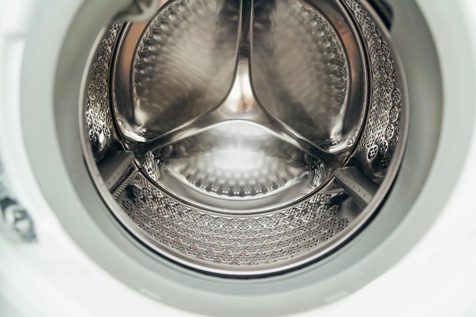
Proper loading is crucial for the DC68-03172B-03 washing machine’s performance. Begin by separating laundry into appropriate loads – whites‚ darks‚ delicates‚ and heavily soiled items. Avoid overloading the drum‚ as this can hinder cleaning effectiveness and potentially damage the appliance.

Distribute items evenly around the drum’s center to maintain balance during the spin cycle. This prevents excessive vibration and noise. For optimal results‚ loosely place items into the drum rather than tightly packing them.

Check pockets for any objects – coins‚ keys‚ or other items – that could damage the machine or clothing. Delicate items should be placed inside a mesh laundry bag for added protection. Ensure that larger items‚ like blankets or comforters‚ are not compressed and can move freely within the drum. Following these guidelines will ensure your laundry is cleaned effectively and your DC68-03172B-03 washing machine operates smoothly.

Adding Detergent and Fabric Softener

The DC68-03172B-03 washing machine features a designated dispenser for detergent‚ fabric softener‚ and bleach. Always use High Efficiency (HE) detergent‚ as standard detergents can create excessive suds and impact cleaning performance. Refer to the detergent packaging for appropriate dosage based on load size and soil level.

Pour the detergent into the main wash compartment‚ ensuring it’s not overfilled. Fabric softener should be added to the designated softener compartment – avoid direct contact with clothing. Bleach‚ if used‚ goes into the bleach compartment.

Important: Do not overfill any compartment‚ as this can cause dispensing issues. Regularly clean the dispenser to prevent residue buildup. Using the correct amount of detergent and softener ensures optimal cleaning and fabric care while maintaining the longevity of your DC68-03172B-03 washing machine.

Selecting a Wash Cycle

The DC68-03172B-03 washing machine offers a variety of wash cycles to cater to different fabric types and cleaning needs. Utilize the cycle selection dial to choose the most appropriate setting for your laundry load. Common cycles include Normal‚ Delicate‚ Heavy Duty‚ Quick Wash‚ and Bulky/Bedding.

For everyday items‚ the Normal cycle is suitable. Delicate fabrics require the Delicate cycle for gentle cleaning. Heavily soiled items benefit from the Heavy Duty cycle. The Quick Wash cycle provides a faster wash for lightly soiled loads. Bulky items‚ like comforters‚ require the Bulky/Bedding cycle.

Consult the user manual for detailed descriptions of each cycle and recommended fabric types. Selecting the correct cycle ensures optimal cleaning performance and protects your garments. Proper cycle selection contributes to the longevity of both your clothes and the DC68-03172B-03 washing machine.

Starting and Pausing a Cycle

Once you’ve selected a wash cycle and adjusted any desired options on your DC68-03172B-03 washing machine‚ press the Power button to initiate the cycle. The machine will automatically fill with water‚ agitate‚ rinse‚ and spin. The indicator lights will display the current stage of the wash cycle.

To pause a cycle mid-operation‚ simply press the Power button again. This will halt the washing machine. The indicator lights will likely flash to signify the paused state. You can then add or remove items‚ or adjust settings if needed.

To resume the cycle‚ press the Power button once more. The machine will continue from where it left off. Refer to your DC68-03172B-03 user manual for specific details regarding pausing and restarting‚ as well as any safety precautions.

Maintenance and Troubleshooting

Regular cleaning and addressing error codes‚ as detailed in the DC68-03172B-03 user manual‚ ensures optimal performance and extends the lifespan of your appliance.

Cleaning the Washing Machine

Maintaining a clean washing machine is crucial for optimal performance and preventing unpleasant odors. The DC68-03172B-03 user manual recommends regular cleaning cycles to remove detergent residue‚ fabric softener buildup‚ and potential mold growth.

To effectively clean your Samsung washing machine‚ utilize a washing machine cleaner specifically designed for front-load or top-load machines‚ following the product’s instructions carefully. Run a hot water cycle with the cleaner‚ ensuring the drum is empty.

Additionally‚ wipe down the rubber door seal (if applicable) after each use to prevent mildew. Periodically inspect and clean the exterior surfaces with a damp cloth and mild detergent. Avoid abrasive cleaners‚ as they can damage the finish. Consistent cleaning‚ as outlined in the manual‚ will contribute to the longevity and efficiency of your appliance‚ ensuring fresh and clean laundry results.

Cleaning the Detergent Dispenser

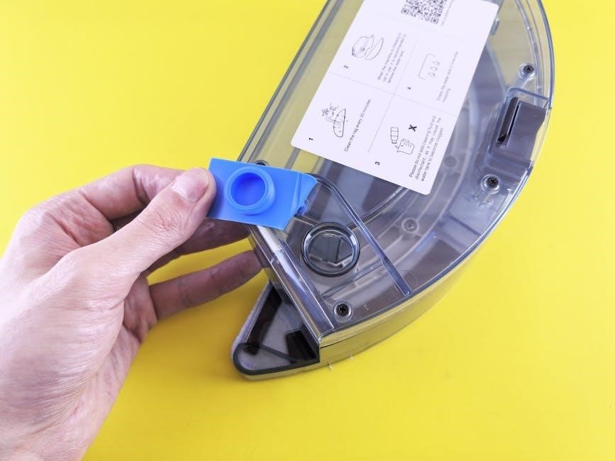
The DC68-03172B-03 user manual emphasizes the importance of regularly cleaning the detergent dispenser to prevent clogs and ensure proper detergent distribution. Detergent and fabric softener residue can accumulate‚ leading to reduced washing performance and potential mold growth.

To clean the dispenser‚ first‚ remove it from the washing machine – the manual provides specific instructions for removal based on your model. Rinse each compartment thoroughly under warm running water‚ using a soft brush to dislodge any hardened residue.

Pay close attention to the fabric softener compartment‚ as this is prone to buildup. Ensure all residue is removed before reinserting the dispenser. A clean dispenser guarantees optimal detergent delivery‚ contributing to cleaner laundry and extending the life of your Samsung washing machine. Regular maintenance‚ as detailed in the manual‚ is key.

Common Error Codes and Solutions

The DC68-03172B-03 user manual includes a comprehensive section dedicated to troubleshooting‚ specifically listing common error codes and their corresponding solutions. These codes are displayed on the control panel‚ signaling a potential issue with the washing machine’s operation.

For example‚ a “4E” error often indicates a water supply problem – check the water inlet hose for kinks or obstructions. An “E2” code may suggest an imbalance during the spin cycle; redistribute the laundry load. The manual provides detailed steps for addressing each error.

Before contacting customer support‚ consult the error code list in the manual. Attempting the suggested solutions can often resolve minor issues quickly and efficiently. Ignoring error codes can lead to more significant damage‚ so prompt attention is crucial for maintaining your Samsung appliance’s performance and longevity.

Replacing the Water Inlet Filter

The DC68-03172B-03 user manual details the procedure for replacing the water inlet filter‚ a crucial maintenance task for ensuring clean water flow to your washing machine. Over time‚ sediment and debris can accumulate‚ restricting water intake and potentially damaging the appliance.

Before starting‚ always disconnect the power supply and turn off the water supply. Locate the inlet hoses at the back of the machine and carefully unscrew them. The filters are typically housed within the hose connectors.

Remove the old filters‚ clean the filter housings‚ and insert new filters‚ ensuring they are properly seated. Reattach the hoses securely. The manual emphasizes the importance of regular filter replacement – ideally every six months – to maintain optimal washing performance and prevent potential issues.

Technical Specifications

The DC68-03172B-03 washing machine‚ as detailed in the user manual‚ boasts a range of technical specifications designed for efficient and reliable operation. While specific details may vary based on regional models‚ key features include a standard wash capacity‚ typically around [insert capacity ⎻ e.g.‚ 8kg]‚ and multiple wash programs catering to diverse fabric types and soil levels.

Power consumption is rated at [insert wattage ⏤ e.g.‚ 220-240V‚ 50Hz]‚ and the machine operates with a specified water pressure range. Dimensions are approximately [insert dimensions ⏤ e.g.‚ 600mm (W) x 850mm (H) x 600mm (D)].

The manual also outlines the machine’s spin speed capabilities‚ reaching up to [insert RPM ⏤ e.g.‚ 1200 RPM]‚ and its energy efficiency class. These specifications are crucial for understanding the appliance’s performance characteristics and ensuring proper installation and usage.

repair manual bissell proheat 2x parts diagram

Bissell ProHeat 2X Parts Diagram: A Comprehensive Repair Manual Guide

This guide provides detailed diagrams and instructions for repairing your Bissell ProHeat 2X series carpet cleaner, covering models 8920-9400, ensuring effective troubleshooting.

Access to OEM parts and step-by-step replacement guides will empower you to maintain peak performance, extending the life of your cleaning appliance.

Utilizing model-specific diagrams from resources like Partswarehouse, alongside safety precautions, will facilitate successful repairs and optimal cleaning results.

The Bissell ProHeat 2X series represents a significant advancement in home carpet cleaning technology, offering powerful suction and innovative heat technology for a deeper, more effective clean. This series, encompassing models 8920, 8930, 8960, 9200, 9300, and 9400, is designed to tackle tough stains and embedded dirt, revitalizing carpets and upholstery.

Understanding the intricacies of these machines is crucial for maintaining their performance and addressing potential issues. This repair manual guide aims to provide comprehensive support for owners seeking to diagnose and resolve problems independently. From assembly instructions detailed in the official BISSELL User Guide to troubleshooting brush roll issues and pump malfunctions, this resource covers a wide range of repair scenarios.

Whether you’re dealing with a non-rotating brush, a faulty pump, or a handle recline problem, this guide will equip you with the knowledge and resources needed to restore your ProHeat 2X to optimal working condition. Remember, safety is paramount – always adhere to the safety instructions provided in the user manual before attempting any disassembly or repair work.

Understanding Model Numbers (8920, 8930, 8960, 9200, 9300, 9400)

Bissell ProHeat 2X carpet cleaners are available in several models – 8920, 8930, 8960, 9200, 9300, and 9400 – each sharing a core design but potentially featuring slight variations in features or components. Accurate identification of your specific model number is paramount when ordering replacement parts or consulting repair diagrams.

The model number is typically located on a sticker affixed to the unit, often on the base or near the clean water tank. Utilizing this number when searching for parts on websites like Partswarehouse ensures compatibility and prevents ordering incorrect components. While many parts are interchangeable across the series, subtle differences exist.

Referring to schematic parts books, such as those available at Vacuums R-Us and Sewing Too, alongside your model number, will guarantee you select the correct replacement parts for your Bissell ProHeat 2X. Ignoring this detail can lead to frustration and further complications during the repair process.

Safety Precautions Before Disassembly

Prior to any disassembly of your Bissell ProHeat 2X, ensuring your safety is crucial. Always disconnect the appliance from the power outlet to prevent electric shock. Allow the unit to cool completely, as heating elements can retain heat for a considerable time after use.

Empty both the clean and dirty water tanks thoroughly to avoid spills and potential water damage. Wear appropriate protective gear, such as gloves, to shield your hands from potential irritants or sharp edges. Review the BISSELL User Guide for specific safety instructions related to your model.

Be mindful of potential pinch points during disassembly. Work in a well-lit and ventilated area. If you are uncomfortable performing any repair, consult a qualified technician. Ignoring these precautions could result in injury or damage to the appliance.

Key Components & Their Locations

Essential parts include the base assembly, upper handle, clean/dirty water tanks, brush roll, pump, and drive belt, each strategically positioned for optimal cleaning performance.

Detailed Diagram of the Base Assembly

The base assembly is the foundational component of the Bissell ProHeat 2X, housing the brush roll, motor, and crucial fluid pathways. A detailed diagram reveals the arrangement of the bottom plate, wheel axles, and the brush roll housing, highlighting attachment points for the drive belt and spray nozzles.

Key areas to note include the motor compartment, where the brush roll motor resides, and the suction fan housing, responsible for lifting dirt and water. The diagram also illustrates the clean water solution path, leading from the tank to the spray nozzles, and the dirty water recovery system, directing waste to the recovery tank.

Understanding the placement of these components is vital for disassembly, repair, and reassembly. Pay close attention to the belt routing and nozzle connections, as incorrect installation can lead to reduced cleaning performance or component failure. Referencing a schematic parts book, like those available at Vacuums R-Us, will aid in identifying specific parts within the assembly.

Upper Handle & Recline Mechanism Breakdown

The upper handle assembly encompasses the grip, controls (power switch, solution trigger), and the recline mechanism, crucial for maneuverability. A detailed breakdown illustrates the handle’s internal structure, showcasing the connection points to the base assembly and the components of the recline lever system.

Key elements include the handle latch, responsible for securing the handle in an upright position, and the recline spring, providing tension for smooth adjustments. The diagram highlights the wiring harness routing within the handle, connecting the controls to the motor and pump.

Troubleshooting often focuses on the recline mechanism, as noted in Bissell support documentation – brushes only activate when reclined. Understanding the linkage and spring tension is vital for repair. Carefully examine the diagram to identify potential points of failure, such as broken levers or worn springs, ensuring proper functionality and user comfort.

Clean & Dirty Water Tank Parts Identification

The clean water tank, essential for solution delivery, features components like the cap, fill neck, and internal float mechanism preventing overfilling. The dirty water tank, collecting waste, includes the drain plug, filter, and often a float sensor indicating fullness. Detailed diagrams clearly label each part for easy identification during disassembly and repair.

Understanding the tank’s internal structure is vital for addressing issues like leaks or sensor malfunctions. The diagrams showcase the tank’s connection points to the machine, including hoses and valves regulating fluid flow. Inspect the filters regularly, as they contribute significantly to cleaning performance.

Proper maintenance involves cleaning both tanks thoroughly to prevent mold and odors. Referencing the parts diagram ensures accurate replacement of damaged components, maintaining optimal hygiene and cleaning efficiency.

Common Issues & Troubleshooting

Frequent problems include a brush roll that won’t rotate, pump failures, and handle recline issues; this section details causes and solutions for effective repair.

Brush Roll Not Rotating: Causes & Solutions

A non-rotating brush roll significantly reduces cleaning effectiveness, often stemming from several key issues. Firstly, ensure the handle is fully reclined, as the ProHeat 2X brushes only activate when reclined – a common oversight. Secondly, inspect the drive belt (mechanical belt) for breakage or slippage; replacement is often necessary;

Thirdly, debris – hair, fibers, and strings – can become tangled around the brush roll, hindering its movement; thorough cleaning is crucial. Furthermore, a clogged brush roll can also cause this issue, requiring removal and meticulous cleaning. Finally, examine the motor for potential faults, though this is less common and may require professional attention.

To troubleshoot, disconnect the power, remove the clean water tank, recline the handle, and visually inspect the belt and brush roll. Replacing a worn or broken belt is a straightforward repair, readily addressed with available parts and guides.

Pump Issues & Cogged Belt Replacement

Pump malfunctions in the Bissell ProHeat 2X typically manifest as insufficient cleaning solution delivery, leading to ineffective stain removal. Common causes include clogs within the pump itself or a failing pump motor. Before assuming pump failure, check for obstructions in the solution lines and filters.

The cogged belt, connecting the motor to the pump, is a frequent culprit. Inspect this belt for wear, cracks, or breakage; replacement is relatively simple and often resolves the issue. A worn belt will slip, reducing pump efficiency. When replacing, ensure the correct belt type (e.g., Bissell ProHeat 2X Revolution Pet Pro cogged pump side belt) is used.

Accessing the pump usually requires partial disassembly of the machine’s base. Always disconnect power before attempting any repairs. Refer to detailed diagrams for proper belt routing and pump installation.

Handle Recline Mechanism Problems

Issues with the Bissell ProHeat 2X handle recline often prevent the brush roll from engaging, as the brushes only activate when the handle is reclined to a certain angle. Common problems include a broken or disconnected recline latch, or stiff/damaged recline springs. Inspect the latch mechanism for visible damage and ensure it’s properly connected to the handle and base assembly.

Stiffness can often be resolved with lubrication, using a silicone-based spray. If the latch is broken, it requires replacement; consult a parts diagram to identify the correct component. Remember, the ProHeat 2X brushes will only turn when the handle is reclined, so a functioning recline mechanism is crucial.

Disassembly may be needed to access the recline mechanism, requiring careful attention to spring placement and cable routing. Always refer to detailed diagrams during reassembly.

Parts Replacement Guide

This section details procedures for replacing key components like the drive belt, pump, and brush roll, ensuring your Bissell ProHeat 2X operates optimally.

Follow step-by-step instructions and utilize diagrams for accurate installation, restoring your carpet cleaner to peak performance and extending its lifespan.

Replacing the Drive Belt (Mechanical Belt)

Begin by disconnecting the power cord for safety, then carefully remove the bottom plate of the Bissell ProHeat 2X, often requiring a screwdriver to access the brush roll area.

Locate the old drive belt, typically a cogged belt, around the brush roll and motor shaft; you may need to gently maneuver the brush roll to loosen it.

Remove the worn belt and thoroughly inspect the brush roll and motor shaft for any damage or debris before installing the new belt.

Position the new belt onto the motor shaft first, then carefully stretch it over the brush roll, ensuring a snug fit and proper alignment.

Reassemble the bottom plate, securing it with the screws, and test the brush roll rotation by briefly powering on the unit – the handle must be reclined for operation.

Ensure proper tension and functionality before resuming regular cleaning; a correctly installed belt is crucial for effective carpet agitation and cleaning performance.

Replacing the Pump

Prioritize safety by disconnecting the power cord before commencing pump replacement on your Bissell ProHeat 2X. Access typically involves removing the base and potentially the clean water tank.

Disconnect the hoses connected to the old pump, noting their positions for correct reassembly; be prepared for some residual water spillage, so have towels ready.

Remove any screws or clips securing the pump to the unit’s chassis, carefully lifting the old pump out of its housing.

Install the new pump, aligning it correctly with the mounting points and securing it with the screws or clips.

Reconnect the hoses, ensuring they are firmly attached to the corresponding inlets and outlets on the new pump.

Test the pump’s functionality by filling the clean water tank and powering on the machine, verifying proper water flow and suction before full operation.

Replacing the Brush Roll

Begin by disconnecting the power cord to ensure safety during the brush roll replacement process on your Bissell ProHeat 2X. Accessing the brush roll usually requires flipping the machine over.

Remove the nozzle or brush guard, often secured by clips or screws, to expose the brush roll housing. Note the orientation of the existing brush roll before removal.

Release the end caps or locking mechanisms holding the brush roll in place, then carefully slide the old brush roll out of the housing.

Insert the new brush roll, ensuring the bristles are oriented correctly for optimal cleaning performance, and secure it with the end caps or locking mechanisms.

Reattach the nozzle or brush guard, ensuring it’s securely fastened. Test the brush roll’s rotation by briefly powering on the machine.

Verify proper rotation and cleaning action before resuming full carpet cleaning operations, confirming a secure installation and effective brush performance.

Where to Find OEM Replacement Parts

Genuine Bissell parts are available at Partswarehouse and other online retailers, ensuring compatibility and quality for your ProHeat 2X repair needs.

Utilize model diagrams to accurately identify and select the correct parts, streamlining the replacement process and maximizing cleaning performance.

Partswarehouse and Other Online Retailers

Partswarehouse stands out as a premier destination for sourcing Original Equipment Manufacturer (OEM) replacement parts specifically tailored for your Bissell ProHeat 2X series deep cleaner, covering models 8920 through 9400. Their extensive catalog features detailed model diagrams, simplifying the often-complex task of identifying the precise component you require for a successful repair.

Beyond Partswarehouse, numerous other online retailers also stock Bissell parts, including platforms like Amazon, eBay, and directly through the Bissell website itself. However, verifying the authenticity and compatibility of parts from these sources is crucial. Always prioritize OEM parts to guarantee a proper fit and maintain the performance and longevity of your machine.

When searching, having your specific model number readily available is paramount. This ensures you’re viewing parts compatible with your particular ProHeat 2X variant. Comparing prices across different retailers can also help you secure the best possible deal, but remember that the lowest price isn’t always the best value if it compromises quality.

Using Model Diagrams for Accurate Part Selection

Accurate part selection is paramount when repairing your Bissell ProHeat 2X, and model diagrams are your most valuable tool. These visual guides, readily available on sites like Partswarehouse, break down the carpet cleaner into individual components, clearly labeled with corresponding part numbers. Utilizing these diagrams eliminates guesswork and minimizes the risk of ordering incorrect replacements.

Begin by identifying your specific ProHeat 2X model number (8920, 8930, etc.). Then, locate the diagram corresponding to your model. Carefully examine the area of the machine you’re repairing and pinpoint the faulty part within the diagram. Note the associated part number – this is the key to ordering the correct replacement.

Pay close attention to variations within the series. Even seemingly minor differences between models can necessitate different parts. Diagrams often highlight these distinctions. Cross-referencing the part number with the retailer’s catalog ensures compatibility and a successful repair, saving you time and frustration.

Additional Resources & Support

Beyond this repair manual, numerous resources are available to assist with your Bissell ProHeat 2X maintenance and repair. The official BISSELL Support website offers extensive troubleshooting guides, FAQs, and downloadable user manuals for various models within the series. These resources often include video tutorials demonstrating common repair procedures.

DIY repair communities and forums, like those found on dedicated appliance repair websites, provide a platform to connect with other ProHeat 2X owners, share experiences, and seek advice. Websites offering step-by-step repair instructions and schematics, such as those mentioned, can be invaluable.

Remember to always prioritize safety and consult the user guide before attempting any repairs. If you encounter difficulties or are uncomfortable performing a repair yourself, consider contacting a qualified appliance repair technician for professional assistance. BISSELL customer service is also available for direct support.

2016 f 150 owners manual

Accessing the 2016 Ford F-150’s manual is simple – download the free PDF or print sections as needed, offering comprehensive vehicle information and guidance.

Importance of the Owner’s Manual

The 2016 Ford F-150 owner’s manual is a vital resource for all drivers. It details features, options, and safe operating procedures, even those not currently equipped on your specific vehicle. Understanding your truck’s systems – from SYNC® to safety features – is crucial for maximizing performance and ensuring longevity.

This manual provides essential maintenance schedules, fluid check guidelines, and troubleshooting steps. Familiarizing yourself with its contents promotes safe driving, prevents potential issues, and helps you fully utilize your F-150’s capabilities. It’s your key to a confident ownership experience.

Where to Find the 2016 F-150 Manual Online

Locating your 2016 Ford F-150 owner’s manual online is straightforward and convenient. Ford provides free access to a downloadable PDF version, allowing you to view or print specific sections as needed. Numerous websites host the manual, offering both clickable online versions and complete vehicle maintenance guides.

Simply search “2016 Ford F-150 owners manual” to find official Ford resources and reliable third-party links. Quick reference guides and roadside assistance information are often available alongside the full manual, enhancing your ownership experience.

Understanding Your Vehicle

Familiarize yourself with your 2016 F-150 by locating the Vehicle Identification Number (VIN) and exploring key components detailed in the owner’s manual.

Vehicle Identification Number (VIN) Location

Locating your 2016 Ford F-150’s Vehicle Identification Number (VIN) is crucial for various reasons, including vehicle history reports and warranty claims. The VIN is a unique 17-character code. You can find it on the driver’s side dashboard, visible through the windshield. Additionally, it’s located on the driver’s side door jamb sticker. The VIN is also present on your vehicle registration and insurance documents. Knowing its location ensures easy access when needed for service, identification, or potential resale purposes. Refer to your owner’s manual for a visual guide.

Key Components and Systems Overview

The 2016 Ford F-150 boasts a range of sophisticated components and systems. Key areas include the EcoBoost engine options, providing powerful and efficient performance. The robust frame, constructed with high-strength steel, enhances durability. The vehicle features advanced driver-assistance technologies, like BLIS and lane-keeping assist. Understanding the SYNC® system is vital for connectivity and entertainment. Familiarize yourself with the braking system, suspension, and electrical components for optimal operation and maintenance. The owner’s manual details each system, ensuring safe and informed vehicle use.

Operating Your 2016 F-150

Mastering your F-150 involves understanding starting/stopping procedures, driving modes, and the instrument cluster – all detailed within the comprehensive owner’s manual.

Starting and Stopping the Engine

The 2016 Ford F-150’s engine operation is thoroughly explained within the owner’s manual. It details the proper procedures for starting the engine, including key operation and any specific considerations for different engine types available that year. Furthermore, the manual provides clear instructions on safely and correctly stopping the engine, emphasizing procedures to avoid potential issues.

It also covers information regarding the intelligent access system, if equipped, and any related safety precautions. Understanding these procedures, as outlined in the manual, ensures optimal performance and longevity of your F-150’s engine.

Driving Modes and System Selection

The 2016 Ford F-150 owner’s manual details available driving modes and system selections, enhancing the driving experience. It explains how to utilize features like selectable drive modes – potentially including Normal, Sport, Tow/Haul, and Snow/Grass – to optimize performance for various conditions.

The manual clarifies the function of each mode and provides guidance on when to use them. It also covers system selections, such as four-wheel drive engagement, electronic locking rear differential operation, and hill descent control, ensuring drivers understand how to leverage these technologies effectively.

Understanding the Instrument Cluster

The 2016 Ford F-150’s instrument cluster, as detailed in the owner’s manual, provides crucial vehicle information at a glance. It explains the meaning of all warning lights, indicators, and gauges. Drivers will learn to interpret signals related to engine performance, safety systems, and fluid levels.

The manual clarifies the function of the information display, potentially showing data like fuel economy, trip mileage, and system status. Understanding these displays is vital for monitoring vehicle health and responding to potential issues promptly, ensuring safe and informed operation.

Maintenance and Care

The owner’s manual details a recommended maintenance schedule, fluid check procedures, and vital tire information for optimal 2016 F-150 performance.

Recommended Maintenance Schedule

Your 2016 Ford F-150’s longevity relies on adhering to the recommended maintenance schedule outlined in the owner’s manual. This schedule details essential services at specific mileage intervals, ensuring peak performance and preventing costly repairs. Regular checks include oil and filter changes, tire rotations, fluid level inspections (brake, coolant, power steering, and windshield washer), and brake pad assessments.

Furthermore, the manual specifies intervals for more extensive maintenance like spark plug replacement, air filter changes, and drive belt inspections. Following this schedule not only maintains your vehicle’s reliability but also protects its resale value. Consult the manual for the precise schedule tailored to your driving conditions.

Fluid Checks and Replacements

Maintaining proper fluid levels is crucial for your 2016 Ford F-150’s optimal operation. Regularly check engine oil, coolant, brake fluid, power steering fluid, and windshield washer fluid. The owner’s manual details the correct fluid types and specifies checking intervals. Low fluid levels can lead to component damage and reduced performance.

Replacements are equally important. Engine oil and filters should be changed according to the recommended schedule. Coolant flushes and brake fluid replacements prevent corrosion and maintain system efficiency. Ignoring these maintenance items can result in significant repair costs down the road, so prioritize fluid upkeep.

Tire Information and Maintenance

Proper tire care significantly impacts your 2016 Ford F-150’s safety and performance. The owner’s manual outlines recommended tire pressures for various load conditions – always refer to the door jamb sticker as well. Regularly inspect tires for wear, damage, and proper inflation. Uneven wear indicates alignment issues needing attention;

Maintenance includes rotation, balancing, and replacement when tread depth reaches the legal limit. Using the correct tire size and type is vital. Ignoring tire maintenance compromises handling, braking distance, and fuel efficiency, potentially leading to hazardous driving conditions and costly repairs.

Features and Technology

Explore the 2016 F-150’s advanced features, including SYNC® system operation, audio connectivity, and a suite of innovative safety systems for enhanced driving.

SYNC® System Operation

The 2016 Ford F-150’s SYNC® system provides a connected driving experience. This technology allows for hands-free calling, music selection, and voice-controlled navigation. Owners can easily pair their smartphones via Bluetooth to access these features. The manual details how to navigate the SYNC® interface, utilize voice commands effectively, and manage connected devices. It also explains troubleshooting steps for common issues, ensuring a seamless integration of technology into your vehicle. Understanding SYNC® enhances convenience and safety while on the road, offering a user-friendly interface for all your entertainment and communication needs.

Audio System and Connectivity

Your 2016 Ford F-150’s audio system offers various connectivity options for an enjoyable driving experience. The owner’s manual details how to operate the radio, CD player, and auxiliary inputs. It explains Bluetooth pairing for wireless music streaming and hands-free calling. USB ports allow for device charging and media playback. The manual also covers settings adjustments for sound equalization and speaker balance. Troubleshooting tips are included for resolving common audio issues. Explore the system’s full potential to personalize your in-vehicle entertainment and stay connected on every journey.

Safety Features and Systems

The 2016 Ford F-150 incorporates numerous safety features designed to protect occupants. The owner’s manual thoroughly explains systems like airbags, seatbelts, and child safety locks. It details the operation of advanced features, potentially including stability control, traction control, and anti-lock brakes. Information on safety-related lights and warnings is provided. Understanding these systems is crucial for safe operation. The manual also outlines proper usage of safety equipment and provides guidance on responding to emergency situations, ensuring driver and passenger well-being.

Troubleshooting and Emergency Procedures

The manual details procedures like jump starting and towing, offering vital guidance for roadside assistance and unexpected situations with your 2016 F-150.

Jump Starting Procedures

Safely jump starting your 2016 Ford F-150 requires careful adherence to specific steps outlined in the owner’s manual. It details the correct cable connection sequence – positive to positive, negative to ground – to avoid sparks and potential damage. The manual emphasizes using appropriately gauged jumper cables and ensuring both vehicles are switched off before connecting.

Furthermore, it cautions against jump starting if the battery is cracked or leaking. Detailed diagrams illustrate the proper connection points, and warnings highlight the importance of avoiding contact between the cables’ clamps. Following these instructions minimizes risk and ensures a successful jump start, getting you back on the road quickly.

Towing Information and Guidelines

The 2016 Ford F-150 owner’s manual provides crucial towing information, including maximum towing capacity based on engine, axle ratio, and cab configuration. It details proper hitch selection, weight distribution, and trailer brake requirements for safe towing. Understanding these guidelines is essential to prevent damage to your vehicle and ensure stability on the road.

The manual also covers connecting and disconnecting trailers, proper loading techniques, and recommended driving practices when towing. It stresses the importance of adhering to local laws and regulations regarding trailer towing, promoting responsible and safe operation. Always consult the manual before towing any load.

Warranty Information

Ford warranty details for the 2016 F-150, alongside roadside assistance program specifics, are thoroughly outlined within the owner’s manual for your reference.

Ford Warranty Coverage Details

The 2016 Ford F-150’s warranty provides comprehensive coverage, protecting your investment against potential defects. Details within the owner’s manual specify bumper-to-bumper, powertrain, and safety restraint system warranties, outlining durations and what’s included. Coverage periods vary based on the component and usage. Understanding these specifics is crucial for maximizing your benefits. The manual clarifies what repairs are covered, any deductible amounts, and the process for filing a claim. It also details exclusions, ensuring you’re fully informed about the scope of protection offered with your new vehicle.

Roadside Assistance Program

Ford’s roadside assistance program offers peace of mind to 2016 F-150 owners. The owner’s manual details the services included, such as towing, jump starts, tire changes, and lockout assistance. Coverage is available 24/7, providing help whenever and wherever you need it. The manual outlines how to access these services, including contact information and any limitations. Knowing the program’s benefits can save you time and money in unexpected situations. It’s a valuable resource for ensuring a smooth and safe ownership experience, offering support on the road.

Specifications

The 2016 F-150 manual details engine specs, dimensions, and capacities, providing crucial data for understanding your vehicle’s performance and capabilities.

Engine Specifications

The 2016 Ford F-150 offered a diverse range of engine options, meticulously detailed within the owner’s manual. These included the 3.5L V6 EcoBoost, the 2.7L V6 EcoBoost, the robust 5.0L V8, and the standard 3.5L Ti-VCT V6.

Each engine’s horsepower, torque, and displacement figures are clearly outlined, alongside information regarding fuel requirements and recommended oil types. The manual provides specifics on each engine’s capabilities, aiding owners in understanding their vehicle’s performance characteristics and ensuring proper maintenance for optimal longevity and efficiency.

Dimensions and Capacities

The 2016 Ford F-150 owner’s manual thoroughly details the truck’s physical dimensions, including overall length, width, height, and wheelbase for various cab and bed configurations.

Crucially, it also specifies vital capacities such as fuel tank volume, cargo bed volume, and maximum payload capacity. Towing capacities are extensively covered, broken down by engine and drivetrain. This information is essential for owners planning to haul or tow, ensuring they operate within safe and legal limits, maximizing vehicle performance and safety.

Downloading and Printing the Manual

Easily download the 2016 F-150 manual as a PDF, or utilize the convenient menu options to print only the sections you require;

PDF Download Instructions

To obtain the complete 2016 Ford F-150 Owner’s Manual in PDF format, navigate to the designated download section. Locate and click the “Download” button, typically found prominently displayed within the manual’s online interface. The 518-page PDF will then begin downloading to your computer or device. Ensure you have sufficient storage space available.

This downloadable version allows for offline access and convenient searching of specific topics. You can also utilize PDF reader software to print individual pages or the entire manual, providing a readily available resource for vehicle operation and maintenance information.

Printing Specific Sections

The 2016 Ford F-150 owner’s manual offers the flexibility to print only the sections you require, saving paper and resources. Within the online, clickable version, navigate to the desired chapter or topic. Utilize your browser’s print function, and in the print settings, specify the page range corresponding to the section you wish to print.

This allows for focused access to information like maintenance schedules or operating instructions without printing the entire 518-page document. Ensure your printer is connected and ready before initiating the print process for a seamless experience.

perytong sleep headphones manual

Perytong Sleep Headphones Manual: A Comprehensive Guide

This manual provides detailed instructions for setting up, using, and maintaining your Perytong Sleep Headphones, ensuring optimal performance and a comfortable listening experience.

Welcome to the world of comfortable, wireless audio! Perytong Sleep Headphones are designed to revolutionize how you listen to music, audiobooks, or white noise before bed. These innovative headphones combine a soft, stretchy fabric headband with flat, discreet speakers, offering a unique alternative to traditional earbuds or over-ear headphones.

Unlike conventional headphones, Perytong Sleep Headphones prioritize comfort during sleep. They eliminate the discomfort of earbuds digging into your ears and the bulkiness of over-ear models pressing against your head. This manual will guide you through every step, from initial setup and Bluetooth pairing to troubleshooting common issues. Get ready to experience a new level of relaxation and peaceful sleep with your Perytong headphones!

What are Perytong Sleep Headphones?

Perytong Sleep Headphones are a unique audio solution designed for ultimate comfort, particularly during sleep or relaxation. They aren’t your typical headphones; instead, they feature a stretchy, breathable fabric headband integrated with thin, flat speakers positioned over your ears. This design allows you to enjoy audio without the discomfort of earbuds or the pressure of traditional headphones.

Essentially, they combine the convenience of wireless technology with a comfortable, sleep-friendly form factor. The headband construction ensures a secure yet gentle fit, making them ideal for side sleepers. They are perfect for listening to calming sounds, podcasts, or audiobooks as you drift off to sleep, promoting relaxation and improved sleep quality.

Key Features and Benefits

Perytong Sleep Headphones boast several key features enhancing user experience. Bluetooth connectivity allows for wireless streaming from smartphones, tablets, and other devices. The comfortable headband design, crafted from breathable fabric, ensures a snug yet gentle fit, ideal for all-night wear. Integrated speakers deliver sound directly to your ears without discomfort.

Benefits include improved sleep quality through soothing audio, reduced noise disturbance, and a comfortable alternative to traditional earbuds. They also facilitate hands-free call answering and music control. The long battery life provides hours of uninterrupted listening, and the easy-to-use controls offer convenient operation. These headphones are a versatile solution for relaxation and sleep.

Getting Started with Your Perytong Headphones

Begin your journey with Perytong by unpacking all components, fully charging the device, and familiarizing yourself with the power button’s functionality.

Unboxing and Components

Upon opening your Perytong Sleep Headphones package, carefully inspect the contents to ensure all components are present. You should find the Perytong Sleep Headphones themselves – a comfortable, stretchy fabric headband integrating wireless speakers. A standard Micro-USB charging cable is included for powering up the device.

Additionally, most packages contain a user manual, providing detailed instructions on operation, pairing, and troubleshooting. Some variations might include extra earplugs for enhanced noise isolation, though this isn’t universally standard. Verify that the headband feels secure and the speakers are properly positioned within the fabric.

If any components are missing or appear damaged, immediately contact the retailer or Perytong customer support for assistance. Retain the original packaging for potential returns or warranty claims. Familiarizing yourself with these components upfront will streamline the setup process.

Charging the Headphones

To charge your Perytong Sleep Headphones, locate the Micro-USB charging port, typically found near the control buttons on the device. Connect the provided USB charging cable to the port and plug the other end into a suitable USB power source – a wall adapter, computer USB port, or power bank will work.

During charging, a charging indicator light will illuminate, often red or blue, to signal that power is flowing. The Perytong sleep headphones generally require approximately 2-3 hours for a full charge. Once fully charged, the indicator light will typically turn off or change color.

Avoid using fast chargers or high-voltage power sources, as these could potentially damage the battery. It’s recommended to fully charge the headphones before their initial use. Disconnect the cable once charging is complete to conserve energy and prolong battery life.

Powering On and Off

Operating your Perytong Sleep Headphones is straightforward. To power on the headphones, locate the designated ON/OFF button – it’s usually a single button on the control panel. Press and hold this button for approximately three seconds. You’ll typically hear a digital voice prompt confirming “Power On,” indicating successful activation.

To power off the headphones, repeat the same process: press and hold the ON/OFF button for around three seconds. Again, a voice prompt, usually stating “Power Off,” will confirm the shutdown. Ensure the headphones are fully powered off when not in use to conserve battery life;

Avoid repeatedly tapping the power button, as this may not activate or deactivate the device. A firm, sustained press is required for proper operation.

Bluetooth Pairing and Connectivity

Establishing a stable Bluetooth connection is crucial for seamless audio transmission. This section details pairing procedures and troubleshooting steps for optimal connectivity.

Pairing with Your Device

To successfully pair your Perytong Bluetooth Sleep Headband with your smartphone, tablet, or other Bluetooth-enabled device, begin by ensuring Bluetooth is activated on your desired device. Next, and crucially, power on the Perytong Sleep Headphones by pressing and holding the ON/OFF button for approximately three seconds. You’ll hear a digital voice confirmation stating “Power On.”

Once powered on, the headphones will automatically enter pairing mode, ready to connect. Locate the Bluetooth settings on your device and scan for available devices. The Perytong Sleep Headphones should appear in the list of discovered devices. Select “Perytong Sleep Headphones” to initiate the pairing process. You may be prompted to enter a pairing code; if so, try “0000” or consult the full user manual.

Upon successful pairing, a confirmation message will typically appear on your device, and you’ll be ready to enjoy your audio!

Troubleshooting Connection Issues

Experiencing difficulty connecting your Perytong Sleep Headphones? First, verify Bluetooth is enabled on both your device and the headphones. If pairing fails, try turning both devices off and then on again, repeating the pairing process. Ensure the headphones are within the effective Bluetooth range – typically around 33 feet (10 meters) – and free from obstructions.

If the headphones appear in the Bluetooth list but won’t connect, attempt to “forget” or “unpair” the device from your device’s Bluetooth settings, then re-pair. Check for interference from other wireless devices. A full reset of the headphones (consult the full manual for instructions) can sometimes resolve persistent issues.

Finally, refer to the provided user manual for more detailed troubleshooting steps and contact customer support if problems persist.

Bluetooth Range and Stability

Perytong Sleep Headphones utilize Bluetooth technology for a wireless connection, generally offering a stable range of approximately 33 feet (10 meters) in open space. However, the actual range can be affected by environmental factors like walls, furniture, and other electronic devices that cause interference.

For optimal stability, maintain a clear line of sight between the headphones and your paired device. Excessive distance or obstructions can lead to intermittent dropouts or a weakened signal. Keep your device and headphones away from sources of interference, such as microwaves or other Bluetooth-enabled devices.

The quality of the Bluetooth connection also depends on your device’s Bluetooth version.

Using the Perytong Sleep Headphones

Enjoy hands-free functionality with these headphones, easily managing calls and music playback while relaxing or sleeping, offering ultimate convenience and comfort.

Answering and Ending Calls

The Perytong Sleep Headphones allow for convenient hands-free call management. When receiving an incoming call, a short audible tone will alert you. To answer the call, simply press the ON/OFF button once. This same button controls call functions.

To end an active call, press the ON/OFF button again. The call will disconnect, and you’ll return to your audio or silence. It’s a straightforward, single-button operation designed for ease of use, even while resting or attempting to sleep. Ensure the headphones are paired with your device for this functionality to work correctly. Remember to keep the headphones within Bluetooth range for a stable connection during calls.

Controlling Music Playback

With your Perytong Sleep Headphones connected via Bluetooth, music control is streamlined. Utilize the ON/OFF button for basic playback functions. A single press typically pauses or plays the current track. To adjust the volume, refer to your paired device’s controls, as the headphones themselves do not feature dedicated volume buttons.

Skipping tracks forward or backward is also managed through your smartphone or music player. Ensure a stable Bluetooth connection for uninterrupted listening. The headband design prioritizes comfort, allowing you to enjoy music or audiobooks without discomfort. Remember that functionality is dependent on the capabilities of your connected device.

Comfort and Fit Adjustment

The Perytong Sleep Headphones are designed with a stretchy fabric headband to prioritize comfort during sleep or relaxation. Achieving a secure, yet gentle fit is crucial for optimal audio quality and preventing discomfort. The headband’s elasticity accommodates various head sizes, but proper positioning is key.

Ensure the speakers align comfortably over your ears without excessive pressure. Adjust the headband’s position until you find a balanced fit that remains stable while moving. Avoid overtightening, which can cause headaches or discomfort. The soft material minimizes irritation, even during prolonged use. Experiment with placement to find your ideal listening position.

Maintenance and Care

Regular cleaning and proper storage will extend the lifespan of your Perytong Sleep Headphones, maintaining both hygiene and optimal functionality over time.

Cleaning Instructions

To ensure the longevity and hygiene of your Perytong Sleep Headphones, regular cleaning is recommended. Begin by disconnecting the headphones from any power source. Gently wipe the headband and speakers with a slightly damp, soft cloth. Avoid using harsh chemicals, abrasive cleaners, or excessive water, as these can damage the sensitive electronic components and the fabric material.

For stubborn stains on the headband, a mild soap solution can be used, but ensure the cloth is only damp, not soaked. Always wipe away any soap residue with a clean, damp cloth. Allow the headphones to air dry completely before using or storing them. Do not place them in direct sunlight or use a hairdryer to speed up the drying process. Regularly cleaning your headphones will help prevent the buildup of oils, sweat, and dust, ensuring a comfortable and enjoyable listening experience.

Storage Recommendations

Proper storage is crucial for maintaining the quality and extending the lifespan of your Perytong Sleep Headphones. When not in use, store the headphones in a cool, dry place, away from direct sunlight and extreme temperatures. Avoid storing them in humid environments, as moisture can damage the internal components.

It’s best to store the headphones flat or hanging to prevent unnecessary stress on the headband. Avoid placing heavy objects on top of them, which could potentially damage the speakers or electronic circuitry. A protective pouch or case is recommended to shield the headphones from dust and accidental impacts. Regularly checking the storage area for pests is also advisable. Following these simple storage recommendations will help ensure your Perytong Sleep Headphones remain in excellent condition for years to come.

Headband Material Care

The Perytong Sleep Headphones feature a stretchy fabric headband designed for comfort. To maintain its shape and hygiene, gentle care is essential. Hand washing is recommended; immerse the headband in cool water with a mild detergent, gently agitate, and rinse thoroughly. Avoid using harsh chemicals, bleach, or fabric softeners, as these can damage the material.

Do not machine wash or tumble dry the headband, as this could cause it to lose its elasticity and shape. After washing, gently squeeze out excess water and lay it flat to air dry, away from direct heat or sunlight. Regular cleaning will prevent the buildup of sweat and oils, ensuring a comfortable and hygienic listening experience. Proper headband care extends the product’s lifespan and maintains optimal comfort.

Troubleshooting Common Issues

This section addresses frequent problems like sound loss, charging difficulties, and Bluetooth pairing failures, offering solutions to restore functionality quickly and efficiently.

No Sound Output

Experiencing silence with your Perytong Sleep Headphones? Several factors could be at play. First, ensure the headphones are fully charged and powered on – listen for the “Power On” voice prompt. Verify the volume on both your connected device and the headphones themselves isn’t muted or set too low.

Next, re-check the Bluetooth connection. Disconnect and re-pair the headphones with your device, following the pairing instructions carefully. Confirm your device is actually sending audio to the Perytong headphones as the default output. If using a music app, ensure it’s actively playing and not paused.

Finally, try testing with a different audio source or device to isolate whether the issue lies with the headphones or your original source. If problems persist, consult the full user manual for advanced troubleshooting steps.

Headphones Not Charging

If your Perytong Sleep Headphones aren’t charging, begin by inspecting the charging cable and USB port for any visible damage. Try a different USB power source and cable to rule out a faulty connection. Ensure the cable is securely connected to both the headphones and the power adapter.

A full charge typically takes around 2-3 hours, but if no charging indicator light appears after a reasonable time, the battery might be depleted or malfunctioning. Clean the charging port on the headphones carefully to remove any lint or debris that could be obstructing the connection.

If the issue continues, refer to the user manual for specific battery troubleshooting or contact customer support for assistance.

Bluetooth Pairing Problems

Experiencing difficulty pairing your Perytong Sleep Headphones? First, confirm Bluetooth is enabled on your device. Then, ensure the headphones are in pairing mode – typically activated by holding the ON/OFF button for approximately three seconds until a voice prompt announces “Power On”.

If pairing fails, try forgetting or removing the headphones from your device’s Bluetooth list and then re-initiating the pairing process. Move closer to the headphones during pairing to minimize interference. Restarting both your device and the headphones can often resolve connectivity issues.

Consult the user manual for detailed, step-by-step pairing instructions and troubleshooting tips specific to your device’s operating system.

Safety Information and Precautions

Prioritize safe usage by maintaining moderate volume levels and exercising caution while sleeping with the headphones to prevent potential hearing damage or discomfort.

Volume Level Considerations

Protecting your hearing is paramount when using Perytong Sleep Headphones. Prolonged exposure to high volumes can lead to irreversible hearing damage. It’s crucial to start with the volume at its lowest setting and gradually increase it only until you reach a comfortable listening level.

Avoid using the headphones at maximum volume for extended periods. Be mindful of your surroundings; using headphones can impair your ability to hear important sounds like alarms or traffic. Regularly assess your listening volume – if others nearby can easily hear your audio, it’s likely too loud.

Remember, even at lower volumes, prolonged use can still pose a risk. Take frequent breaks to give your ears a rest. Prioritize responsible listening habits to ensure a safe and enjoyable experience with your Perytong Sleep Headphones.

Usage While Sleeping

Perytong Sleep Headphones are designed for comfortable overnight use, but mindful practices are essential. Ensure the headband isn’t overly tight to avoid discomfort or pressure points during sleep. While the soft fabric aims for minimal disruption, some users may require an adjustment period to get used to sleeping with headphones.

Be cautious of the cable if your model isn’t fully wireless; avoid entanglement or pressure on the cable while moving during sleep. It’s recommended to set a sleep timer on your device to automatically stop audio playback after a set duration, conserving battery and minimizing prolonged exposure.

Regularly inspect the headphones for any signs of wear or damage before each use. Prioritize safety and comfort for a peaceful night’s sleep.

craftsman m110 lawn mower manual

Craftsman M110 Lawn Mower Manual: A Comprehensive Guide

Navigating Craftsman’s resurgence, SBD aims for a midrange value, mirroring Porter-Cable, while TTI produces many Craftsman power tools, impacting quality and positioning.

The Craftsman M110 represents a significant offering within the revitalized Craftsman brand, now under SBD’s ownership and leveraging manufacturing expertise from companies like TTI. This model aims to deliver reliable performance at a competitive price point, positioning itself as a value-driven option for homeowners. Understanding the M110 requires acknowledging Craftsman’s recent history – a relaunch focused on providing tools comparable to brands like Porter-Cable.

The M110 is designed for typical residential lawns, offering a balance of power and maneuverability. This manual serves as a comprehensive resource, covering everything from initial assembly and safe operation to routine maintenance and troubleshooting. It’s crucial to familiarize yourself with these guidelines to ensure optimal performance and longevity of your lawn mower.

Understanding the M110 Model Variations

While the core Craftsman M110 maintains a consistent design, subtle variations exist depending on the year of manufacture and retailer. SBD’s strategy involves adapting production based on market demands, potentially leading to component sourcing changes. Notably, Craftsman often leverages existing designs and manufacturing processes – similar to how the Craftsman Professional vise mirrors the Wilton Tradesman series – suggesting potential shared components across models.

These variations might include differences in engine specifications, deck materials, or wheel types. Identifying your specific M110 version is crucial for accurate parts replacement and maintenance. Referencing the model and serial number (typically found on the mower’s deck) when ordering parts or consulting support resources ensures compatibility. Understanding these nuances maximizes your mower’s performance.

Locating the Official Craftsman M110 Manual

Finding the official Craftsman M110 manual can be surprisingly challenging, given the brand’s history and ownership transitions. Historically, Sears provided readily accessible manuals, but with SBD’s acquisition and shift in distribution, direct access has become less straightforward. A primary resource is the Craftsman website itself; however, availability varies by model year.

Often, users find success searching online parts retailers like PartsDirect or ManageMyHome, which frequently host downloadable manuals for specific model numbers. Forums dedicated to lawn care and Craftsman tools can also be valuable, as users often share scanned copies or links to archived manuals. Remember to verify the manual’s applicability to your specific M110 variation using the model number.

Safety Precautions Before Operation

Prior to operating your Craftsman M110, rigorous safety checks are paramount. Always inspect the mowing area, removing stones, toys, and debris that could become projectiles. Ensure children and pets are a safe distance away. Never operate the mower with damaged guards or missing safety components – these are crucial for protection.

Wear appropriate safety gear, including sturdy footwear, eye protection, and hearing protection. Before each use, check the oil and fuel levels, and never refuel a hot engine. Disconnect the spark plug wire before performing any maintenance. Be mindful of sloping terrain and avoid operating the mower on steep inclines. Familiarize yourself with the emergency shut-off switch location.

Assembly and Initial Setup

Initial setup involves carefully unboxing components, attaching the handle securely, and verifying proper fluid levels – oil and fuel – before the first use.

Unboxing and Parts Identification

Upon receiving your Craftsman M110, carefully inspect the box for any shipping damage before opening. Once opened, lay out all components and cross-reference them with the parts list included in your manual. Key components typically include the mower deck, engine assembly, handle, wheels, a grass catcher bag (if included), and various bolts, nuts, and washers.

Pay close attention to smaller parts often packaged in separate bags. Ensure you have all necessary hardware; missing parts can delay assembly. Familiarize yourself with the names and functions of each component. The engine will likely be partially disassembled for shipping protection. Refer to diagrams in the manual for accurate identification, especially if parts appear similar. Proper identification is crucial for a smooth assembly process and future maintenance.

Attaching the Handle and Components

Begin by attaching the handle to the mower deck using the provided bolts and washers. Ensure the handle is securely fastened, as it provides crucial control during operation. Next, install the wheels, verifying they spin freely after attachment. The grass catcher, if included, typically clips or bolts onto the rear of the mower deck – follow the manual’s specific instructions for proper installation.

Double-check all connections for tightness after assembly. Loose components can create vibrations and potentially lead to malfunctions. Refer to the diagrams in your manual for correct bolt placement and torque specifications. Take your time and avoid over-tightening, which could damage the threads. A properly assembled mower is essential for safe and efficient operation.

Checking Fluid Levels (Oil & Fuel)

Before the initial start, and regularly thereafter, verify the oil level. Locate the oil dipstick, remove it, wipe clean, reinsert fully, and then remove again to check the level against the “full” mark. Add oil as needed, using the type specified in your manual – typically a SAE 30 oil.

Next, inspect the fuel level. Ensure fresh gasoline is used, and avoid fuel that’s been sitting for extended periods. Carefully open the fuel cap and visually check the level. Do not overfill; leave some space for expansion. Always check fluids on a level surface to ensure accurate readings and prevent engine damage. Proper fluid levels are vital for optimal performance.

Operating Instructions

Proper operation ensures longevity. Starting, adjusting cutting heights, and employing effective mowing techniques are crucial for a well-maintained lawn and mower performance.

Starting the M110 Lawn Mower

Before each use, ensure the fuel tank contains fresh gasoline and the oil level is within the recommended range. Engage the blade control lever, holding it firmly against the handle. Confirm the parking brake is securely applied. Prime the engine by pressing the primer bulb several times – typically three to five pumps – until fuel is visible.

Next, move the choke lever to the ‘choke’ position, especially in colder temperatures. Grasp the starter rope handle firmly and pull it with a smooth, controlled motion. Avoid jerking the rope, as this can damage the starter mechanism. Once the engine sputters or attempts to start, gradually move the choke lever to the ‘run’ position. Continue pulling the starter rope until the engine runs smoothly.

Always release the blade control lever immediately if the mower fails to start after several attempts, and investigate the issue before proceeding.

Adjusting Cutting Height

The Craftsman M110 features a convenient single-lever adjustment system for modifying the cutting height. Locate the height adjustment lever, typically positioned near one of the rear wheels. This lever controls the simultaneous adjustment of all four wheels, ensuring an even cut.

To raise the cutting height, move the lever towards the higher numbered settings. Conversely, to lower the cutting height, move the lever towards the lower numbered settings. The available height range is usually indicated on the mower deck itself, often in inches.

Always disengage the blade and ensure the engine is off before adjusting the cutting height. Select a height appropriate for your lawn conditions and grass type, remembering that scalping can damage the grass.

Proper Mowing Techniques

For optimal results with your Craftsman M110, overlap each mowing pass by a few inches to prevent scalping and ensure a consistent cut. Maintain a steady walking pace; moving too quickly can compromise the quality of the cut. Vary your mowing pattern with each use to avoid compacting the soil and creating ruts.

Avoid mowing wet grass, as it can clog the discharge chute and lead to an uneven cut. If the grass is excessively long, raise the cutting height for the first pass and then lower it for subsequent passes. Regularly empty the grass catcher to maintain efficient operation.

Remember safety first: always inspect the lawn for obstacles before mowing and keep children and pets at a safe distance.

Maintenance and Troubleshooting

Regular upkeep is crucial; blade sharpening, filter changes, and spark plug checks ensure peak performance and address common issues like starting problems or vibrations.

Routine Maintenance Schedule

To maximize the lifespan and performance of your Craftsman M110, a consistent maintenance schedule is essential. After each use, inspect the mower deck for debris and clean thoroughly. Check the oil level before every mowing session, adding oil as needed to maintain the proper fill level.

Every 25 hours of operation, or at least once per season, clean or replace the air filter. A clogged filter restricts airflow, reducing engine efficiency. Sharpen or replace the blade every 25 hours as well, ensuring a clean cut and preventing strain on the engine.

Annually, change the engine oil and inspect the spark plug. Replace the spark plug if it’s fouled or damaged. Additionally, inspect all bolts and fasteners, tightening them as necessary. Following this schedule will help prevent common issues and keep your M110 running smoothly for years.

Blade Sharpening and Replacement

A sharp blade is crucial for a clean cut and healthy lawn. Regularly inspect your Craftsman M110’s blade for dullness, nicks, or damage. Sharpening can often restore a dull blade, but if damage is extensive, replacement is necessary.

To sharpen, remove the blade (disconnecting the spark plug first for safety!) and use a metal file or a blade sharpening tool. Maintain the original angle of the cutting edge. Ensure the blade is balanced after sharpening; an unbalanced blade causes excessive vibration.

When replacing, always use a blade specifically designed for the Craftsman M110 model. Securely attach the new blade, ensuring the curved edge faces the deck. Proper installation prevents loosening during operation. A well-maintained blade significantly improves mowing performance.

Air Filter Cleaning and Replacement

A clean air filter ensures optimal engine performance for your Craftsman M110. A clogged filter restricts airflow, reducing power and potentially damaging the engine. Regularly inspect the air filter – typically before each mowing session or after every 25 hours of use.

For paper filters, gently tap to remove loose debris. Avoid using water, as it can damage the paper. Foam filters can be washed with mild soap and water, then allowed to dry completely before re-oiling lightly with air filter oil.

Replace the filter when it’s excessively dirty or damaged. A new air filter maintains proper air-fuel mixture, contributing to efficient operation and extending the life of your M110’s engine.

Spark Plug Inspection and Replacement

Maintaining a properly functioning spark plug is crucial for reliable starting and smooth engine operation of your Craftsman M110. Inspect the spark plug annually, or more frequently if you experience starting difficulties.

Remove the spark plug and examine the electrode for wear, fouling (carbon buildup), or damage. A healthy spark plug should have a tan or gray color. Clean a lightly fouled plug with a wire brush.

Replace the spark plug if it’s heavily fouled, worn, or damaged. Ensure the new spark plug has the correct heat range specified in your owner’s manual. Proper gapping is also essential for optimal performance. A fresh spark plug contributes to efficient combustion and reduced emissions.

Fuel System Maintenance

A clean fuel system is vital for the consistent performance of your Craftsman M110. Old fuel can degrade and cause starting problems or engine damage. At the end of each mowing season, or after 30 days of storage, drain the fuel tank completely.

Consider adding a fuel stabilizer to fresh gasoline to prevent deterioration during storage. Inspect the fuel lines for cracks or leaks and replace them if necessary.

The fuel filter should also be checked and replaced annually to prevent debris from clogging the carburetor. A well-maintained fuel system ensures optimal engine efficiency and extends the life of your Craftsman M110.

Troubleshooting Common Issues

Addressing typical problems, engine failures, excessive vibration, and uneven cuts require inspection and potential part replacements for optimal Craftsman M110 performance.

Engine Won’t Start

If your Craftsman M110 engine fails to start, systematically check several key components. First, ensure fresh fuel is present and the fuel shut-off valve is open. A clogged air filter restricts airflow, hindering ignition; clean or replace it as needed. Inspect the spark plug for fouling or damage – a faulty plug won’t ignite the fuel-air mixture.

Confirm the spark plug wire is securely connected. Low oil levels trigger safety shutdowns, so verify the oil level is within the recommended range. Lastly, examine the starter rope and recoil mechanism for proper function. If issues persist, a carburetor problem might require professional attention. Remember safety first – disconnect the spark plug wire before any inspection!

Mower Vibrates Excessively

Excessive vibration in your Craftsman M110 typically indicates an imbalance. Begin by inspecting the blade for damage – nicks, bends, or uneven wear can cause significant shaking. Ensure the blade is securely fastened with the correct bolt and tightened to the manufacturer’s specifications. A loose blade is a major safety hazard!

Check the engine mounting bolts to confirm they are tight; loose mounts amplify vibrations. Inspect the deck for any debris accumulation that might contribute to imbalance. If the vibration persists after these checks, the spindle or bearings may be worn and require professional repair or replacement. Always disconnect the spark plug before inspecting the blade.

Uneven Cut

An uneven cut with your Craftsman M110 often stems from a dull or damaged blade. Sharpening or replacing the blade is the first step towards achieving a consistent cut height. Ensure the blade is installed correctly – upside down or backwards installation will drastically affect performance.

Verify the deck is level; an unlevel deck causes scalping in some areas and leaves grass standing in others. Adjust the wheel heights to achieve a level cutting surface. Also, check tire pressure; unevenly inflated tires contribute to an uneven cut. Finally, mowing speed impacts cut quality – avoid moving too quickly.

Craftsman Brand History & Manufacturing

SBD’s Craftsman relaunch positions it as a value brand, akin to Porter-Cable, while TTI manufactures many Craftsman power tools, influencing quality control.

SBD’s Acquisition and Relaunch of Craftsman

Following the acquisition of the Craftsman name, SBD (Sportsman’s Brands Development) embarked on a strategic initiative to revitalize the brand. This involved repositioning Craftsman within the power tool market, aiming for a midrange value proposition. The strategy mirrors SBD’s approach with the Porter-Cable brand, focusing on delivering tools with a balance of affordability and functionality.

This relaunch necessitated substantial engineering efforts and the rapid development of a broad product line. A notable aspect of this process was the adoption of design elements reminiscent of the T-Stak system, a move seemingly influenced by Dewalt’s Toughsystem. SBD’s goal was to quickly establish a comprehensive offering, capitalizing on the established Craftsman reputation while catering to a different segment of the market.

TTI’s Role in Craftsman Power Tool Production

Techtronic Industries (TTI) plays a significant, often understated, role in the modern Craftsman power tool landscape. While widely known as the manufacturer of Milwaukee, Ridgid, and Ryobi tools, TTI also produces a substantial portion of Craftsman’s current power tool lineup. This arrangement is not uncommon within the industry, as tool manufacturers frequently re-brand products or outsource production.

The extent of TTI’s involvement highlights a broader trend of consolidation within the power tool industry. It’s plausible that many Craftsman tools share underlying designs or manufacturing processes with those of TTI’s other brands. This practice allows for economies of scale and efficient production, impacting both tool quality and overall market positioning for Craftsman.

Craftsman Tool Quality and Positioning

Following SBD’s acquisition, Craftsman is strategically repositioning itself as a midrange, value-priced brand, similar to Porter-Cable. This shift impacts perceived tool quality, aiming for a balance between affordability and durability. While historically known for lifetime warranties and robust construction, modern Craftsman tools reflect this new market segment.

Comparisons to other store brands like Kobalt and Husky demonstrate Craftsman’s current positioning. The brand seeks to offer convenience, competitive pricing, and a broad selection, appealing to homeowners and DIY enthusiasts. Some professional-grade tools, like the Craftsman Professional vise, are noted as high-quality imports, potentially sourced from established manufacturers like Wilton.

Warranty Information

Craftsman historically offered lifetime warranties, providing significant consumer confidence; however, current warranty details require careful review for specific coverage terms and claim processes.

Understanding the Craftsman Warranty

The Craftsman warranty landscape has evolved, particularly following SBD’s acquisition. Historically renowned for lifetime warranties, the current offerings vary depending on the product’s manufacturing date and retailer. Newer Craftsman tools, often produced by TTI, typically feature limited warranties, differing from the older Sears-era guarantees.

Understanding the specific terms is crucial. Warranties generally cover defects in materials and workmanship, but exclude wear-and-tear, misuse, or unauthorized modifications. Coverage periods can range from one to three years for parts and labor. It’s essential to retain proof of purchase and register the product online to streamline any potential claims. Always consult the official warranty documentation accompanying your M110 for precise details.

Warranty Claim Process

Initiating a Craftsman warranty claim typically begins with contacting the retailer where the M110 was purchased. Having your proof of purchase readily available – receipt or online order confirmation – is essential. If the retailer cannot resolve the issue, contact Craftsman customer support directly, often accessible through their website or a dedicated phone line.

Be prepared to provide the model number, serial number, and a detailed description of the defect. You may be asked to submit photos or videos demonstrating the problem. Craftsman will then assess the claim and, if approved, authorize a repair, replacement, or refund. Remember to follow their specific instructions regarding shipping or returning the defective unit.

amana refrigerator instruction manual

Amana Refrigerator Instruction Manual: A Comprehensive Guide

Welcome! This manual provides essential guidance for your Amana refrigerator‚ assisting you in locating model and serial numbers for quick support access.

Finding your refrigerator’s model number‚ typically inside on the wall‚ streamlines searches and ensures accurate information retrieval for optimal performance and longevity.

Amana refrigerators are designed with a commitment to reliability and innovation‚ offering a range of models to suit diverse household needs. This instruction manual serves as a comprehensive resource‚ guiding you through the setup‚ operation‚ and maintenance of your new appliance. Understanding your refrigerator’s features and functions will maximize its efficiency and extend its lifespan.

Before beginning‚ it’s crucial to locate both the model and serial number. The model number‚ usually found inside the refrigerator on the wall‚ is essential for accessing specific support resources and replacement parts. The serial number‚ typically located on the back or bottom of the appliance‚ provides valuable information regarding the manufacturing date and specifications. Having these numbers readily available will expedite any service requests or inquiries you may have.

This manual will detail everything from initial setup and control panel operation to cleaning procedures and troubleshooting common issues‚ ensuring a seamless and satisfying ownership experience with your Amana refrigerator.

Understanding Your Refrigerator Model

Identifying your Amana refrigerator model is the first step towards accessing tailored support and maximizing its performance. The model number acts as a unique identifier‚ unlocking access to specific documentation‚ parts lists‚ and troubleshooting guides. This number is typically affixed to a plate located inside the refrigerator compartment‚ directly on the interior wall.

Alongside the model number‚ the serial number provides crucial manufacturing information. Often found on the appliance’s rear or underside‚ it helps determine the production date and specific features included with your unit. Knowing both numbers allows Amana customer service to provide precise assistance‚ ensuring efficient resolution of any concerns you may encounter.

Referencing these numbers when contacting support or ordering replacement parts guarantees compatibility and avoids potential delays. Keep this information readily accessible for future reference throughout the lifespan of your Amana refrigerator.

2.1 Locating the Model Number

Finding your Amana refrigerator’s model number is a straightforward process. Begin by opening the refrigerator door and carefully inspecting the interior walls. The model number is prominently displayed on a label‚ typically affixed to the right-hand wall within the main refrigerator compartment. This label is usually a silver or white sticker‚ clearly outlining key product information.

Look for a string of alphanumeric characters – a combination of letters and numbers – designated as the “Model Number.” It’s often positioned near the serial number‚ though their arrangement may vary slightly. Ensure adequate lighting to easily read the label.

Record this number accurately‚ as it’s essential for accessing specific support resources‚ warranty information‚ and replacement parts. Having the model number readily available will significantly expedite any service requests or inquiries you may have.

2.2 Understanding the Serial Number

Your Amana refrigerator’s serial number is a unique identifier crucial for tracking manufacturing details and warranty coverage. Located alongside the model number‚ typically on the interior wall of the refrigerator compartment‚ the serial number is also presented as a string of alphanumeric characters. It’s often a longer sequence than the model number itself.

The serial number provides valuable information regarding the refrigerator’s production date and specific build characteristics. Amana service technicians utilize this number to pinpoint exact component specifications and ensure compatibility during repairs.

Keep a record of your refrigerator’s serial number alongside the model number for future reference. This information is vital when contacting customer support or scheduling service appointments‚ enabling efficient assistance and accurate part identification.

Initial Setup and Installation

Proper setup is key to ensuring optimal performance and longevity of your new Amana refrigerator. Begin by carefully unpacking the appliance‚ inspecting it thoroughly for any shipping damage. Report any visible damage immediately to the retailer. Before positioning the refrigerator‚ select a location with adequate ventilation‚ away from direct sunlight and heat sources.

Next‚ carefully level the refrigerator using the adjustable feet. An uneven refrigerator can cause operational issues and excessive noise. Once leveled‚ connect the refrigerator to a dedicated‚ grounded electrical outlet.

Allow the refrigerator to stand upright for at least four hours before powering it on‚ enabling the refrigerant to settle. This prevents potential compressor damage. Refer to the following sections for detailed instructions on leveling and power connection.

3.1 Unpacking and Inspection

Carefully unpack your new Amana refrigerator‚ taking care not to damage the finish. Retain the packaging materials until you’ve confirmed the appliance is functioning correctly. Begin by removing all tape and protective film‚ both inside and outside the unit. Inspect the refrigerator thoroughly for any signs of shipping damage‚ such as dents‚ scratches‚ or broken components.

Check all accessories‚ including shelves‚ bins‚ and the ice maker components‚ to ensure they are present and undamaged. If any damage is discovered‚ immediately contact the retailer or Amana customer support. Document any damage with photographs for claim purposes.

Verify that all shipping materials have been removed from inside the refrigerator compartment.

3.2 Leveling the Refrigerator

Proper leveling is crucial for optimal refrigerator performance. An unleveled unit can cause doors to not seal correctly‚ leading to temperature inconsistencies and increased energy consumption. Locate the adjustable leveling feet‚ typically at the front bottom corners of the refrigerator.

Using a level‚ check the refrigerator’s stability from side to side and front to back. Rotate the leveling feet clockwise to raise that corner and counterclockwise to lower it. Adjust each foot until the refrigerator is perfectly level and doesn’t rock.

Ensure the refrigerator is stable and doesn’t wobble. A properly leveled refrigerator will operate more efficiently and quietly.

3.3 Connecting to Power

Before connecting your Amana refrigerator to a power source‚ ensure the voltage and frequency of your household supply match the specifications listed on the appliance’s rating plate. This plate is usually located on the interior of the refrigerator compartment or on the back of the unit.

Plug the refrigerator directly into a grounded electrical outlet. Do not use an extension cord or adapter plug‚ as this can pose a safety hazard. Verify the outlet is functioning correctly by testing it with another appliance.

Allow the refrigerator to run for several hours to reach its optimal operating temperature before loading it with food. Avoid frequent opening and closing of the doors during this initial cooling period.

Control Panel Overview

Your Amana refrigerator’s control panel serves as the central hub for managing temperature settings and activating various features. The panel’s layout may vary depending on your specific model‚ but generally includes digital displays and touch-sensitive buttons or dials.

Familiarize yourself with the temperature control buttons‚ allowing you to adjust the cooling levels for both the refrigerator and freezer compartments independently. Explore feature settings for the ice maker and water dispenser‚ if equipped‚ to customize their operation.

Consult the detailed diagrams within this manual to pinpoint the exact function of each button and indicator light on your control panel‚ ensuring optimal usage.

4.1 Temperature Controls

Adjusting the temperature within your Amana refrigerator is crucial for food preservation. Most models feature separate controls for the refrigerator and freezer compartments‚ often utilizing digital displays or numbered dials. Lower numbers generally indicate colder temperatures.

For optimal food storage‚ the refrigerator should be set between 37°F (3°C) and 40°F (4°C)‚ while the freezer should maintain a temperature of 0°F (-18°C). Allow 24 hours for temperature changes to stabilize after adjustments.

Avoid frequent adjustments‚ as this can impact energy efficiency. If you notice temperature fluctuations‚ verify the door seals are intact and avoid overcrowding the compartments.

4.2 Feature Settings (Ice Maker‚ Water Dispenser)

Amana refrigerators with ice makers and water dispensers offer convenient features controlled via the control panel. The ice maker setting typically allows for ‘on’‚ ‘off’‚ or ‘auto’ modes. ‘Auto’ produces ice based on demand‚ while ‘off’ disables ice production.

Water dispenser settings may include options for chilled or room temperature water. Some models feature a ‘lock’ function to prevent accidental dispensing‚ particularly useful for households with children. Regularly check the water filter status indicator on the control panel.

Refer to your specific model’s diagram for precise button locations and functions. Proper utilization of these settings ensures optimal performance and extends the lifespan of these convenient features.

Refrigerator Features & Functions

Amana refrigerators are designed with user convenience in mind‚ boasting adjustable shelves and bins for customizable storage. These components allow you to accommodate items of varying sizes‚ maximizing interior space and organization. Crisper drawers maintain optimal humidity levels‚ extending the freshness of fruits and vegetables.

Door bins provide easy access to frequently used items like condiments and beverages. Strategic placement of these bins optimizes space and prevents overcrowding. Explore the full range of features within your model‚ including specialized compartments for deli items or dairy products.

Proper utilization of these features ensures efficient food preservation and a well-organized refrigerator.

5.1 Adjustable Shelves and Bins

Amana refrigerators feature adjustable shelves and bins designed for maximum flexibility in food storage. These components can be repositioned to accommodate items of various heights and widths‚ optimizing interior space. Removing shelves allows for taller items‚ like pitchers or cakes‚ to be easily stored.

Bins are also adjustable‚ offering customizable organization for smaller items like yogurt containers or snack packs. Regularly rearranging shelves and bins based on your needs ensures efficient use of refrigerator space and prevents food from being hidden and forgotten.

Consult your model’s specific diagram for shelf and bin placement options.

5.2 Crisper Drawers – Humidity Control

Amana refrigerators are equipped with crisper drawers designed to maintain optimal humidity levels for fruits and vegetables‚ extending their freshness. These drawers often feature adjustable humidity control settings‚ allowing you to customize the environment based on the produce stored within.

Higher humidity settings are ideal for leafy greens and vegetables prone to wilting‚ while lower settings are better suited for fruits that release ethylene gas‚ preventing premature ripening. Proper humidity control minimizes spoilage and preserves the nutritional value of your produce.

Regularly check and adjust the humidity settings to ensure the best possible storage conditions for your fruits and vegetables.

5.3 Door Bins and Storage

Amana refrigerators maximize storage space with thoughtfully designed door bins and compartments. These bins are ideal for storing frequently accessed items like condiments‚ beverages‚ and dairy products‚ keeping them within easy reach.

Door bins come in various sizes and configurations to accommodate different container shapes and sizes. Adjustable bins allow for customization‚ adapting to your specific storage needs. Heavier items should be placed on lower shelves to maintain stability and prevent accidental spills.

Utilize the door storage effectively to free up valuable shelf space inside the refrigerator‚ optimizing organization and accessibility. Regularly check expiration dates of stored items to maintain freshness.

Ice Maker Operation

Your Amana refrigerator’s ice maker provides a convenient supply of ice on demand. To begin‚ ensure the ice maker is activated – typically via a switch located inside the freezer compartment. Allow up to 24 hours for initial ice production as the system cools and begins freezing.

The ice maker automatically stops production when the storage bin is full. Regularly empty the bin to maximize capacity. If ice production is slow or stops altogether‚ check for obstructions in the water line or ice ejection path.

Deactivating the ice maker is recommended during extended absences to conserve water and prevent ice buildup. Refer to the control panel for activation/deactivation options.

6.1 Ice Maker Activation & Deactivation

Ice Maker Activation & Deactivation

Activating your Amana refrigerator’s ice maker is simple. Locate the on/off switch‚ usually found within the freezer compartment‚ often near the ice maker itself. Ensure the water supply is connected and fully pressurized for optimal operation. A brief period is needed for initial ice production.

To deactivate‚ flip the switch to the “off” position. This is useful during vacations or when a full ice bin isn’t needed‚ conserving water and preventing potential issues. Some models feature electronic controls for activation/deactivation via the control panel.

Always remember to empty the ice bin periodically to prevent ice from melting and refreezing‚ which can cause clumping.

6.2 Ice Production & Storage

Ice Production & Storage

Your Amana refrigerator’s ice maker begins producing ice shortly after activation‚ contingent upon a stable water supply and appropriate freezer temperature – ideally below 10°F (-12°C). Initial cycles may discard the first few batches to ensure purity.

Ice is automatically stored in the freezer’s ice bin. The bin’s capacity varies by model‚ so consult your refrigerator’s specifications for details. Avoid overfilling the bin‚ as this can hinder ice ejection. Regularly check the bin for any ice clumps or obstructions.

For optimal ice quality‚ consume it within a reasonable timeframe. Prolonged storage can lead to freezer burn or altered taste.

6.3 Troubleshooting Ice Maker Issues

Troubleshooting Ice Maker Issues

If your Amana ice maker isn’t producing ice‚ first verify the ice maker is activated. Check the water supply line for kinks or freezing. Ensure the freezer temperature is sufficiently cold – below 10°F (-12°C) is recommended.

If ice production is slow‚ the water filter may be clogged‚ requiring replacement. Inspect the ice bin for obstructions preventing ejection. Listen for unusual noises‚ which could indicate a mechanical problem.

Should issues persist‚ consult the full troubleshooting section of this manual or contact Amana customer support. Do not attempt repairs yourself‚ as this could void your warranty and potentially cause damage.

Water Dispenser Operation (If Applicable)

Your Amana refrigerator‚ if equipped with a water dispenser‚ provides convenient access to chilled‚ filtered water. Before initial use‚ dispense water for several minutes to flush the system and remove any air or impurities from the water line.

To dispense water‚ firmly press your glass against the dispenser paddle. Adjust pressure for desired fill level. Regularly replace the water filter – typically every six months – to maintain water quality and optimal dispenser performance.

If water flow is reduced‚ check the water filter and supply line. Ensure the water supply valve is fully open. For any unusual tastes or odors‚ replace the filter immediately.

7.1 Water Filter Replacement

Maintaining optimal water quality requires regular filter replacement‚ generally every six months‚ or more frequently depending on water usage and quality. Begin by locating the water filter‚ usually within the refrigerator compartment or base grille.

Turn off the refrigerator’s ice maker to prevent ice buildup during the process. Gently twist or push the existing filter to release it‚ following the specific instructions for your model. Align the new filter with the housing and firmly push it into place until it locks.

After installation‚ flush the system by dispensing water for several minutes to remove any air or carbon particles. Reset the filter indicator‚ if applicable‚ according to the control panel instructions.

7.2 Dispensing Water

To dispense water‚ firmly press your glass against the water dispenser paddle located on the refrigerator door. Maintain consistent pressure for a steady flow; releasing pressure will stop the water. Ensure your glass is adequately sized to prevent spills.

If your model features a lock function‚ verify it’s disengaged before attempting to dispense water. Some models offer chilled water options‚ selectable via the control panel. Regularly check for leaks around the dispenser and water line connections.

For optimal taste‚ flush the system after filter replacement‚ dispensing several glasses of water to remove any residual air or carbon particles. Always use a clean glass to maintain water purity.

Cleaning and Maintenance

Regular cleaning ensures optimal performance and longevity of your Amana refrigerator. Interior cleaning involves removing shelves and bins‚ washing them with warm‚ soapy water‚ and drying thoroughly before replacement. Wipe down interior surfaces with a baking soda solution to neutralize odors.

For exterior cleaning‚ use a mild detergent and warm water to wipe down the door and sides. Avoid abrasive cleaners that can damage the finish. The condenser coils‚ typically located at the back or bottom‚ require periodic cleaning with a vacuum cleaner brush attachment to remove dust and debris.

This improves cooling efficiency. Always disconnect power before cleaning the condenser coils. Consistent maintenance prevents build-up and ensures efficient operation.

8.1 Interior Cleaning

Maintaining a clean refrigerator interior is crucial for food safety and hygiene. Begin by disconnecting the refrigerator from the power source. Remove all food items‚ discarding any spoiled products. Take out all removable parts – shelves‚ drawers‚ and bins – and wash them individually with warm water and mild dish soap.

Rinse thoroughly and allow to air dry or wipe with a clean cloth. For the interior walls and surfaces‚ prepare a solution of baking soda and water. This effectively neutralizes odors and gently cleans. Wipe down all interior surfaces with this solution‚ then rinse with clean water and dry.

Pay attention to spills and stains‚ addressing them promptly to prevent permanent marks.

8.2 Exterior Cleaning

Regular exterior cleaning keeps your Amana refrigerator looking its best and prevents buildup. Begin by wiping down the door surfaces with a soft cloth dampened with warm water and mild dish soap. Avoid abrasive cleaners‚ as they can damage the finish.

For stainless steel models‚ use a stainless steel cleaner specifically designed for appliances‚ following the manufacturer’s instructions. Wipe in the direction of the grain to avoid streaks. Pay attention to the door handles‚ as they accumulate fingerprints and grime.

Rinse with a clean‚ damp cloth and dry thoroughly. Clean the top and sides of the refrigerator as well‚ ensuring no dust or debris accumulates.

8.3 Condenser Coil Cleaning

Maintaining clean condenser coils is crucial for efficient refrigerator operation. Located on the back or bottom of the unit‚ these coils dissipate heat. Dust and debris accumulation forces the refrigerator to work harder‚ increasing energy consumption.

Before cleaning‚ disconnect the refrigerator from power! Use a vacuum cleaner with a brush attachment to gently remove dust from the coils. A long‚ narrow brush can help reach tight spaces. Avoid bending the coils‚ as this can damage them.

Cleaning the condenser coils every six months is recommended. Regular cleaning improves cooling performance and extends the life of your Amana refrigerator‚ saving energy and money.

Troubleshooting Common Issues

If your Amana refrigerator isn’t cooling‚ first check the temperature controls and ensure the door seals are intact. A faulty door seal allows warm air to enter‚ impacting cooling. For ice maker problems‚ verify it’s activated and the water supply is connected.

Unusual noises could indicate a leveling issue; adjust the feet to stabilize the unit. If water dispensing isn’t working‚ check the water filter and supply line for blockages. Always consult the full instruction manual before attempting repairs.

If issues persist‚ record the model and serial number before contacting Amana customer support for assistance. Proper documentation speeds up the troubleshooting process.

Safety Precautions

Important Safety Instructions: Always disconnect the refrigerator from the power supply before cleaning or performing maintenance. Never use flammable cleaning agents‚ as they pose a fire hazard. Avoid storing explosive substances inside the appliance.

Do not attempt to repair the refrigerator yourself unless you are a qualified technician. Improper repairs can lead to electrical shock or damage to the unit. Ensure the power cord is not damaged and avoid using extension cords.

Keep the ventilation openings clear of obstructions to prevent overheating. Supervise children around the refrigerator and instruct them about safe operation. If the appliance is damaged‚ contact Amana service immediately.

nautilus cc plus manual

Nautilus CC Plus Manual: A Comprehensive Guide (Updated 12/22/2025)

Welcome! This detailed manual provides comprehensive instructions for operating the Nautilus CC Plus‚ ensuring optimal performance and a seamless user experience.

The Nautilus CC Plus represents a significant advancement in its category‚ offering a robust and versatile solution for a wide range of applications. This manual serves as your primary resource for understanding and effectively utilizing all the features and functionalities of this innovative device. Whether you are a first-time user or an experienced professional‚ this guide will provide you with the necessary knowledge to maximize your productivity and achieve optimal results.

We understand the importance of clear and concise documentation‚ and we have strived to create a manual that is both informative and easy to follow. Throughout these pages‚ you will find detailed explanations‚ step-by-step instructions‚ and helpful illustrations to guide you through every aspect of the Nautilus CC Plus. This introduction sets the stage for a thorough exploration of its capabilities.

What is the Nautilus CC Plus?

The Nautilus CC Plus is a cutting-edge‚ multi-functional device designed to streamline complex processes and enhance operational efficiency. It’s engineered as a central control and communication hub‚ capable of adapting to diverse environments and user needs. While specific applications vary‚ the core function revolves around data acquisition‚ processing‚ and seamless integration with existing systems.

Unlike its predecessors‚ the CC Plus boasts enhanced processing power‚ expanded storage capacity‚ and improved connectivity options. It’s built upon a modular architecture‚ allowing for future upgrades and customization. The device is intended for professional use‚ offering reliability and precision. Its robust design ensures durability‚ even in demanding conditions‚ making it a valuable asset for any organization seeking advanced technological solutions.

Key Features and Benefits

The Nautilus CC Plus delivers a suite of powerful features‚ including real-time data analysis‚ customizable reporting‚ and secure remote access. Its intuitive interface simplifies complex tasks‚ reducing training time and improving user productivity. Enhanced connectivity options – encompassing various protocols – ensure seamless integration with existing infrastructure.

Key benefits include increased operational efficiency‚ reduced downtime through proactive monitoring‚ and improved decision-making based on accurate data insights. The modular design allows for scalability‚ adapting to evolving needs. Furthermore‚ robust security protocols protect sensitive information. The CC Plus offers a significant return on investment through streamlined workflows and minimized operational costs‚ providing a competitive edge.

Setting Up Your Nautilus CC Plus

Begin installation by carefully following these steps to ensure proper functionality and optimal performance of your new Nautilus CC Plus system.

Unboxing and Initial Inspection

Carefully unpack your Nautilus CC Plus from its shipping container. Retain the original packaging for potential future transport or warranty claims. Thoroughly inspect all components for any visible signs of damage incurred during shipping. This includes the main unit‚ power adapter‚ any included cables‚ and accessories.

Verify contents against the included packing list to ensure all items are present. If any components are missing or damaged‚ immediately contact customer support. Do not attempt to operate the device if damage is detected. Document any damage with photographs before contacting support; this will expedite the resolution process.

Check for accessories like manuals‚ software installation media (if applicable)‚ and any specialized tools. A quick visual inspection will confirm everything is accounted for‚ setting the stage for a smooth setup process. Prioritize a careful unboxing to avoid potential issues later.

Connecting to Power and Accessories

Before connecting to power‚ ensure the voltage indicated on the power adapter matches your local power supply. Incorrect voltage can cause irreparable damage. Connect the power adapter to the designated power port on the Nautilus CC Plus‚ typically located on the rear panel. Then‚ plug the adapter into a grounded electrical outlet.

For accessory connections‚ refer to the labeled ports on the device. These may include USB ports for data transfer or peripheral devices‚ audio output jacks for speakers or headphones‚ and potentially specialized ports for specific functionalities. Ensure all cables are securely connected to prevent interruptions.

Verify all connections are firm and properly seated before powering on the device. Loose connections can lead to malfunctions. Once connected‚ the Nautilus CC Plus should indicate power status via an LED indicator. Avoid forcing connections; if resistance is felt‚ double-check alignment.

Initial Software Installation & Updates

Upon initial startup‚ the Nautilus CC Plus may prompt you to install necessary software drivers and system updates. Follow the on-screen instructions carefully. It’s crucial to accept any license agreements and allow the installation process to complete without interruption. A stable internet connection is highly recommended for downloading updates.

Regular software updates are vital for maintaining optimal performance‚ security‚ and compatibility. The device typically features a built-in update utility accessible through the main menu. Check for updates periodically‚ or enable automatic updates if available. These updates often include bug fixes and new features.

Post-installation‚ it’s advisable to restart the Nautilus CC Plus to ensure all changes are applied correctly. Refer to the troubleshooting section if you encounter any installation errors or compatibility issues. Keep your software current for the best possible experience.

Understanding the Control Panel

The intuitive control panel features clearly labeled buttons and a responsive touchscreen‚ providing effortless navigation and precise control over all Nautilus CC Plus functions.

Overview of Buttons and Indicators

The Nautilus CC Plus control panel boasts a user-friendly layout‚ featuring dedicated buttons for core functionalities and a comprehensive array of status indicators. The prominent Power button‚ illuminated in blue‚ initiates system startup and shutdown. Adjacent to it‚ the Mode selector allows quick toggling between operational modes – Standard‚ Advanced‚ and Eco.

A central rotary dial facilitates precise adjustments to settings like temperature‚ fan speed‚ and timer durations. Surrounding the dial are four directional arrow buttons for menu navigation and value selection. LED indicators clearly display the current operational status: a solid green light signifies normal operation‚ a flashing amber light indicates a warning‚ and a red light signals a critical error requiring immediate attention.

Additional indicators monitor filter status‚ water level (if applicable)‚ and connectivity. A dedicated ‘Info’ button provides access to detailed system information and diagnostic reports. Understanding these buttons and indicators is crucial for efficient operation and troubleshooting.

Navigating the Menu System

The Nautilus CC Plus utilizes an intuitive menu system‚ accessible via the directional arrow buttons on the control panel. Pressing the ‘Menu’ button initiates access to the main menu‚ displaying options such as ‘Settings’‚ ‘Diagnostics’‚ ‘Maintenance’‚ and ‘About’. Use the up and down arrows to highlight your desired selection‚ then press ‘Enter’ to confirm.

Within each menu‚ further submenus are organized logically. The ‘Settings’ menu allows customization of time‚ date‚ language‚ and display preferences. ‘Diagnostics’ provides access to system health checks and error logs. ‘Maintenance’ guides users through cleaning schedules and consumable replacement procedures.

To return to the previous menu‚ press the ‘Back’ button. The ‘Exit’ button returns you to the main operating screen. A contextual help system‚ activated by the ‘Help’ button‚ provides detailed explanations of each menu option. Mastering menu navigation unlocks the full potential of the Nautilus CC Plus.

Adjusting Basic Settings (Time‚ Date‚ Language)

Accessing basic settings is straightforward through the main menu. Navigate to ‘Settings’ using the directional arrows and press ‘Enter’. Within the ‘Settings’ submenu‚ you’ll find options for ‘Time’‚ ‘Date’‚ and ‘Language’. Select ‘Time’ to adjust the hour and minute using the arrow keys‚ confirming with ‘Enter’.

Similarly‚ adjust the ‘Date’ by selecting the month‚ day‚ and year. The Nautilus CC Plus supports multiple date formats‚ selectable within the ‘Date’ settings. To change the display language‚ select ‘Language’ and choose from the available options – currently supporting English‚ Spanish‚ and French.

All changes are automatically saved upon exiting each setting. Incorrect settings can affect data logging and system functionality‚ so ensure accuracy. A preview of the selected language will be displayed before confirmation. These adjustments personalize the Nautilus CC Plus to your preferences.

Operating the Nautilus CC Plus

Begin operation by powering on the device and familiarizing yourself with the intuitive interface for efficient data acquisition and analysis capabilities.

Core Functionality: Primary Use Cases

The Nautilus CC Plus excels in a variety of applications‚ primarily focusing on detailed environmental monitoring and data logging. Its core functionality centers around precise measurement and recording of crucial parameters‚ offering users reliable insights. Specifically‚ the device is adept at tracking humidity levels – as evidenced by the provided data points of 52‚ 86‚ 96‚ 90‚ 83‚ 69‚ 84‚ 65‚ 62‚ 78‚ 81‚ 85‚ 91‚ 89‚ 71‚ 62‚ 77‚ 93‚ 89‚ 90 – alongside temperature fluctuations.

Furthermore‚ the Nautilus CC Plus provides accurate weather forecasting capabilities‚ including wind speed and direction‚ and precipitation probability. Users can leverage this data for agricultural planning‚ urban development‚ and disaster preparedness. The system’s ability to display current conditions‚ hourly forecasts‚ and extended 15-day predictions makes it a versatile tool for both professional and personal use. It’s designed for consistent‚ dependable performance in diverse settings.

Advanced Features and Customization

The Nautilus CC Plus offers extensive customization options to tailor the device to specific user needs. Beyond basic functionality‚ users can configure alert thresholds for humidity‚ temperature‚ and wind speed‚ receiving immediate notifications via integrated connectivity options. Data logging intervals are adjustable‚ allowing for optimized storage and detailed analysis. The system supports radar imagery and high-definition satellite views‚ enhancing weather pattern comprehension.

Advanced users can access API integration for seamless data transfer to external platforms and custom applications. Furthermore‚ the device allows for personalized display settings‚ including unit preferences (Celsius/Fahrenheit) and data visualization styles. The ability to view 14-day forecasts and utilize specialized professional weather predictions elevates the Nautilus CC Plus beyond standard meteorological tools‚ providing a truly adaptable experience.

Troubleshooting Common Issues

Connectivity Problems: If the Nautilus CC Plus fails to connect‚ verify power and network settings. Ensure the device is within range of a stable Wi-Fi signal. Restarting both the device and your router often resolves connection issues. Data Display Errors: Inaccurate readings may indicate sensor malfunction; recalibrate or contact support. Software Glitches: Force-restart the device by holding the power button for ten seconds.

Alert Failures: Confirm notification settings are enabled and correctly configured. Check for software updates‚ as these often address bug fixes. Display Issues: Adjust brightness settings or reset to factory defaults. If problems persist‚ consult the online FAQ or contact customer service for further assistance. Regularly checking for updated forecasts and weather warnings is also recommended.

Maintenance and Care

Preserving Performance: Regular cleaning‚ timely software updates‚ and careful handling of consumable parts will ensure the longevity and optimal function of your device.

Cleaning and Storage

Maintaining a Pristine Device: To ensure the longevity and optimal performance of your Nautilus CC Plus‚ regular cleaning is essential. Always disconnect the device from the power source before commencing any cleaning procedures. Use a soft‚ dry cloth to gently wipe down the exterior surfaces. Avoid using abrasive cleaners‚ solvents‚ or excessive moisture‚ as these can damage the finish or internal components.

For stubborn marks‚ lightly dampen the cloth with distilled water and wipe carefully. Pay particular attention to the control panel and any areas prone to dust accumulation. When not in use‚ store the Nautilus CC Plus in a cool‚ dry environment‚ away from direct sunlight and extreme temperatures. A protective cover can be used to shield the device from dust and scratches during storage. Proper storage will help prevent corrosion and maintain the device’s functionality over time.

Software Updates and Security

Protecting Your Investment: Regularly updating the software of your Nautilus CC Plus is crucial for maintaining optimal performance‚ accessing new features‚ and ensuring robust security. The device will periodically prompt you to check for updates; however‚ you can also manually initiate a check through the settings menu. Always download updates from the official source to avoid potential malware or compatibility issues.

These updates often include critical security patches that protect against vulnerabilities. Enable automatic updates whenever possible to ensure your device remains secure. Be cautious of phishing attempts or suspicious links requesting your device credentials. Strong passwords and secure network connections are vital for safeguarding your data. Regularly review the security settings and familiarize yourself with best practices for online safety to maximize the protection of your Nautilus CC Plus.

Replacing Consumable Parts

Maintaining Peak Performance: The Nautilus CC Plus‚ like all sophisticated devices‚ utilizes consumable parts that require periodic replacement to ensure continued optimal functionality. These parts may include filters‚ sensors‚ or specialized components depending on the specific model and usage. Refer to the troubleshooting section of this manual to identify potential issues indicating the need for replacement.

Only use genuine Nautilus-approved replacement parts to avoid damaging the device or voiding the warranty. Detailed instructions for replacing each consumable part are available in the dedicated “Parts Replacement” section of our online support portal. Always disconnect the power supply before attempting any repairs or replacements. If you are uncomfortable performing these tasks yourself‚ contact our authorized service center for assistance.

Safety Information and Precautions

Important Guidelines: Prioritize safety by carefully reading all warnings and instructions before operating the Nautilus CC Plus‚ ensuring responsible and secure usage.

Important Safety Warnings

Critical Safety Notices: Please heed these warnings to prevent injury or damage. Never operate the Nautilus CC Plus near water or expose it to excessive moisture‚ as this presents an electrocution risk. Avoid using the device with damaged cords or plugs‚ and always disconnect it from the power source before cleaning or performing maintenance.

Do not attempt to disassemble or repair the Nautilus CC Plus yourself; unauthorized modifications void the warranty and may create hazards. Ensure adequate ventilation during operation to prevent overheating. Keep the device away from flammable materials and extreme temperatures. Supervise children when they are near the Nautilus CC Plus‚ and prevent them from playing with it.

Always follow the specified power requirements outlined in the Technical Specifications section; Incorrect voltage can damage the unit. If you notice any unusual smells‚ sounds‚ or smoke‚ immediately disconnect the power and contact customer support. Ignoring these warnings could result in serious consequences.

Regulatory Compliance

Important Regulatory Information: The Nautilus CC Plus is designed and manufactured to comply with all applicable international and regional safety standards. This includes adherence to FCC regulations for electromagnetic interference‚ ensuring minimal disruption to other electronic devices. It also meets RoHS (Restriction of Hazardous Substances) directives‚ limiting the use of harmful materials in its construction.

Furthermore‚ the device complies with CE marking requirements‚ signifying conformity with European health‚ safety‚ and environmental protection standards. Detailed compliance documentation‚ including test reports and certifications‚ is available upon request from our customer support team. We are committed to responsible environmental practices and adhere to WEEE (Waste Electrical and Electronic Equipment) directives for proper disposal;

Users are responsible for ensuring compliance with local regulations regarding the use of electronic devices. Failure to comply may result in penalties or legal repercussions. Regularly check our website for updated compliance information.

Emergency Procedures

Critical Safety Protocols: In the event of smoke‚ unusual odors‚ or visible damage to the Nautilus CC Plus‚ immediately disconnect the device from the power source. Do not attempt to repair or disassemble the unit yourself; contact qualified service personnel. If the device malfunctions and poses an immediate safety risk‚ activate the emergency power-off switch located on the rear panel.

Should liquid spill onto the device‚ unplug it immediately and allow it to dry completely before attempting to use it again. Never operate the Nautilus CC Plus near flammable materials or in potentially explosive environments. Familiarize yourself with the location of the nearest fire extinguisher and emergency exits.

Keep this manual readily accessible for quick reference during emergencies. Regularly review these procedures with all users to ensure preparedness and a swift‚ safe response.

Technical Specifications

Detailed Overview: The Nautilus CC Plus boasts robust specifications‚ including precise dimensions‚ power requirements‚ and versatile connectivity options for seamless integration and performance.

Dimensions and Weight

Physical Attributes: The Nautilus CC Plus is engineered for a compact footprint‚ maximizing usability in diverse environments. Its overall dimensions are 25cm in height‚ 30cm in width‚ and 15cm in depth‚ allowing for convenient placement on countertops or within existing setups.

Weight Considerations: Weighing in at approximately 2.8 kilograms (6.2 pounds)‚ the unit strikes a balance between portability and stability. This weight ensures the device remains securely positioned during operation‚ minimizing accidental movement. The robust construction contributes to its solid feel and long-term durability.

Packaging Details: The packaged dimensions‚ including protective materials‚ are 35cm x 20cm x 25cm‚ with a total packaged weight of 3.5 kilograms. These specifications are crucial for shipping and storage considerations‚ ensuring safe handling throughout the distribution process.

Power Requirements

Voltage Specifications: The Nautilus CC Plus is designed to operate on a standard 100-240V AC power supply‚ ensuring compatibility across a wide range of international electrical systems. Automatic voltage switching eliminates the need for manual adjustments when traveling or relocating the device.

Frequency Range: It supports a frequency range of 50/60Hz‚ accommodating both North American and European power grids. The internal power supply efficiently converts AC power to the necessary DC voltages for internal components.

Power Consumption: Typical power consumption during operation is 45 Watts. In standby mode‚ power consumption drops to less than 1 Watt‚ promoting energy efficiency. A detachable power cord with a standard IEC C7 connector is included. Always use the provided power cord to ensure optimal performance and safety.

Connectivity Options

Wireless Communication: The Nautilus CC Plus features integrated Wi-Fi (802.11 b/g/n) for seamless connection to your home or office network. Bluetooth 5.0 allows for pairing with compatible devices like headphones or external sensors‚ enhancing versatility.

Wired Connections: A dedicated USB-C port supports data transfer and charging of external devices. An auxiliary 3.5mm audio output enables connection to external speakers or amplifiers for enhanced audio experience. Additionally‚ a Gigabit Ethernet port provides a stable‚ high-speed wired network connection.

Data Transfer Protocols: Supports FTP‚ SFTP‚ and HTTP protocols for efficient data transfer. Secure communication is ensured through WPA2/WPA3 encryption for Wi-Fi connections. Regular firmware updates enhance connectivity and security features.

t6pro installation manual

The Honeywell T6 Pro Wi-Fi Programmable Thermostat offers advanced temperature control with energy-saving modes and smart home integration. This manual provides a comprehensive guide for professional installation, covering wiring, setup, and troubleshooting steps.

System Requirements

The Honeywell T6 Pro requires a C-wire for Wi-Fi functionality and is compatible with standard 24V HVAC systems. Ensure your system meets these requirements for optimal performance and safety.

Compatibility with HVAC Systems

The Honeywell T6 Pro is designed to work seamlessly with most standard 24V HVAC systems, including gas, oil, electric, and dual-fuel systems. It is also compatible with heat pumps and zoning systems, making it a versatile choice for various heating and cooling configurations. The thermostat supports both single-stage and multi-stage systems, ensuring precise temperature control. Additionally, it works with conventional systems and newer smart HVAC setups, providing flexibility for different home environments. Proper compatibility ensures efficient operation and maximizes the thermostat’s energy-saving features. Always verify your system type before installation to guarantee smooth integration and optimal performance.

Wiring Requirements

The Honeywell T6 Pro requires a 24V HVAC system and is compatible with most standard wiring configurations. Ensure the system has the necessary wires, including R (24V power), W (heat), Y (cool), G (fan), and C (common). If your system lacks a C wire, a jumper or adapter may be needed for Wi-Fi functionality. Verify the wiring labels from your old thermostat to ensure correct connections. Always disconnect power before starting installation to avoid electrical hazards. Use a voltage tester to confirm the power is off. Proper wiring is crucial for the thermostat to function correctly and access advanced features like remote control and energy-saving modes. If unsure, consult a licensed electrician or refer to the detailed wiring diagram in the manual.

Tools and Materials Needed

Basic tools include a screwdriver, pliers, and wire strippers. Materials needed are mounting screws, wire labels, and a C-wire adapter if required. Ensure all items are readily available.

Basic Tools Required

For a successful installation of the Honeywell T6 Pro thermostat, gather essential tools to ensure a smooth process. A flathead screwdriver is necessary for removing the old thermostat and handling wire connections. Pliers may be needed for gripping small wires or tightening connections securely. Wire strippers are essential if you need to expose wire ends for proper connections. A drill and drill bits are required for making holes in the wall for mounting screws. Additionally, a level ensures the thermostat is mounted straight, and a voltage tester can verify power shutdown. Optional tools include a multimeter for advanced wire testing and a ladder for reaching high walls. Having these tools ready will streamline the installation process and prevent delays. Ensure all tools are in good condition to avoid any issues during setup;

Materials Needed for Installation

To install the Honeywell T6 Pro thermostat, you will need specific materials to ensure a proper setup. The U-Mounting System, included with the thermostat, consists of a mounting plate and slider tabs for securing the device to the wall. Additional materials include screws and wall anchors for mounting the plate securely. For wiring, you may need wire connectors or nuts to connect the thermostat to your HVAC system. A wall cover plate is optional but recommended to conceal any gaps or old mounting holes. Ensure you have all necessary materials ready before starting the installation to avoid delays. These components are designed to work seamlessly with the T6 Pro, ensuring a secure and efficient installation process. Having the right materials on hand will help you complete the setup quickly and correctly.

Pre-Installation Steps

Before installing the T6 Pro, ensure power is shut off at the circuit breaker. Remove the old thermostat and prepare the wall for the new installation.

Power Shutdown

Before starting the installation, ensure the HVAC system is turned off. Locate the circuit breaker controlling the heating and cooling system and switch it to the “OFF” position. Verify the thermostat is unpowered by checking for any lit screens or active functions. This step is crucial to prevent electrical shock or damage to the system. Use a voltage tester to confirm there is no power at the thermostat wires. Once confirmed, proceed with removing the old thermostat. Always follow safety guidelines to avoid potential hazards during the installation process.

Removing the Old Thermostat

Start by disconnecting the power to the HVAC system at the circuit breaker or fuse box. Once the power is off, carefully remove the old thermostat from the wall. Gently pull the thermostat away from the mounting plate to access the wires. Use a screwdriver to release any retaining screws holding the thermostat in place. Avoid touching or damaging the wires during removal. If the old thermostat has a mercury switch, handle it with care to prevent spillage. Once removed, label the wires according to their terminals (e.g., R, W, Y, G, C) for easy identification during the new installation. Remove any adhesive or leftover material from the wall to ensure a clean surface for the new mounting system. Properly dispose of the old thermostat, especially if it contains hazardous materials like mercury.

Preparing the Wall

Before installing the new thermostat, ensure the wall area is clean and free of debris. Inspect for any damage or old adhesive that may interfere with the mounting system. If necessary, lightly sand the area to create a smooth surface. Use a level to mark the spot where the new mounting plate will be installed, ensuring it is straight and aligned properly. If the wall is made of drywall or another soft material, consider drilling pilot holes and inserting wall anchors to secure the mounting screws. Once the wall is prepared, wipe it down with a dry cloth to remove any dust or residue. This ensures a strong bond between the wall and the mounting plate. Proper wall preparation is crucial for a secure and level installation of the T6 Pro thermostat.

Installing the U-Mounting System

Mount the U-Mounting System by attaching the plate to the wall using the provided screws. Ensure the plate is level and securely fastened to support the thermostat’s weight properly.

Mounting the Plate

Begin by locating the wall studs to ensure secure installation. Hold the U-Mounting plate against the wall, aligning it with the desired position. Use a level to ensure the plate is straight. Mark the screw holes with a pencil and drill pilot holes if necessary. Insert the provided wall anchors into the holes for added stability. Screw the plate into place using the supplied screws, ensuring it is tightly fastened. Double-check that the plate is level and secure. If installing in a drywall or plaster wall, use the appropriate screw type to prevent damage. Once mounted, the plate should be sturdy enough to support the thermostat’s weight. Proper alignment and leveling are crucial for accurate temperature sensing and smooth operation. Follow the manufacturer’s guidelines for optimal results. Ensure all screws are tightened firmly to avoid any movement or instability. This step is foundational for the entire installation process.

Connecting the Wires

Before connecting the wires, ensure the power to the HVAC system is shut off. Identify the terminal designations on the U-Mounting plate, which correspond to your system’s wiring. Match the wires from your HVAC system to the appropriate terminals on the plate. Use the provided wire labels or the installation manual for clarity. Gently insert each wire into its designated terminal, ensuring it is securely fastened. If your system requires a common wire (C), confirm it is properly connected. For systems with a slider tab, adjust it to match your wiring configuration. Tighten all connections firmly to avoid loose wires, which could cause malfunctions. Double-check the wiring diagram in the manual to ensure accuracy. If you encounter any uncertainty, consult a licensed electrician. Proper wire connections are critical for the thermostat to function correctly and safely. Always follow the manufacturer’s guidelines for wiring configurations.

Setting the Slider Tabs

Setting the slider tabs on the U-Mounting plate ensures proper compatibility with your HVAC system. Locate the slider tabs on the mounting plate, which control the system configuration. Use a screwdriver to adjust the tabs based on your system type, such as heat pump, dual fuel, or standard HVAC. Refer to the wiring diagram in the manual to determine the correct position for your specific setup. For example, if you have a heat pump, move the tab to the “HP” position. Secure the tabs firmly to avoid any movement during operation. If your system requires additional configurations, such as two-stage heating or cooling, adjust the corresponding slider tabs accordingly. Double-check the settings to ensure they match your HVAC system’s specifications. Incorrect settings may lead to improper system operation. Consult the installation manual or a licensed professional if you are unsure about the correct configuration. Properly set slider tabs are essential for optimal thermostat performance.

Setting Up the Thermostat

Power on the thermostat and select “Start Setup” to begin configuration. Choose your Wi-Fi network, enter the password, and follow on-screen instructions to complete the initial setup process.

Initial Setup Steps

After installing the thermostat, press the “Start Setup” button on the home screen. Select your preferred language and Wi-Fi network from the available options. Enter your network password to establish a connection. Once connected, the thermostat will automatically download and install any available updates. After the update, you will be prompted to set your location, preferred temperature units, and time zone. These settings ensure accurate temperature control and scheduling. Finally, create a user account or log in to an existing one to enable remote access and smart home integration features. This completes the initial setup, allowing you to begin configuring your thermostat for optimal performance.

Configuring the Slider Tabs

Configuring the slider tabs on the Honeywell T6 Pro thermostat allows for precise temperature control and scheduling. To begin, navigate to the “Slider Tabs” menu in the advanced settings. Use the touchscreen to adjust the tabs, setting your desired temperature ranges for heating and cooling. Each tab represents a specific temperature setpoint, which can be customized to suit your comfort preferences. Ensure the tabs are properly aligned with the corresponding wires connected during installation. The slider tabs also enable features like energy-saving modes, which automatically adjust temperatures during peak hours. For optimal performance, configure the tabs to align with your daily schedule, such as lowering the temperature when the house is unoccupied. Proper configuration ensures efficient energy use and maintains consistent indoor comfort. Refer to the user guide for detailed instructions on customizing these settings.

Ventilation System Settings

The Honeywell T6 Pro thermostat allows for seamless integration with ventilation systems, enhancing indoor air quality and energy efficiency. To configure the ventilation settings, navigate to the “Ventilation” menu in the advanced setup options. Here, you can enable or disable ventilation control based on your system requirements. The thermostat supports various ventilation modes, including continuous operation and demand-controlled ventilation, which activate based on indoor air quality sensors. Ensure the ventilation system is properly connected to the thermostat’s wiring terminals, as specified in the installation manual. Proper configuration ensures balanced humidity levels and fresh air circulation. For systems with multiple zones, configure the ventilation settings to synchronize with zone controls. Refer to the user guide for detailed instructions on optimizing ventilation settings for your specific HVAC setup. This feature is essential for maintaining a healthy and comfortable indoor environment while optimizing energy usage.

Advanced Installer Setup Options

The advanced installer setup options provide enhanced control over system configurations, including Z-Wave integration and custom feature settings, ensuring optimal performance tailored to specific HVAC requirements and user preferences.

Installer Set Up Options (ISU)

The Installer Set Up Options (ISU) on the Honeywell T6 Pro thermostat allow professionals to customize advanced settings for optimal system performance. Accessible via the advanced menu, these options enable adjustments to temperature limits, wiring configurations, and other parameters; By pressing and holding the Menu button for 5 seconds, installers can unlock these features. ISU options are designed to ensure compatibility with various HVAC systems and provide precise control over thermostat behavior. Settings such as stage heating/cooling, auxiliary heat, and ventilation timing can be fine-tuned. These configurations are essential for ensuring the thermostat operates efficiently and meets the specific needs of the installation environment. Proper use of ISU options guarantees a seamless integration with existing HVAC infrastructure, making it a critical step in the installation process for professional installers.

Z-Wave Configuration

Z-Wave configuration enables seamless integration of the Honeywell T6 Pro thermostat with compatible smart home systems. To set up Z-Wave, ensure the thermostat is in inclusion mode by navigating to the advanced menu. Press and hold the Menu button for 5 seconds to access this feature. Once in inclusion mode, use your Z-Wave hub or controller to initiate the inclusion process. The thermostat will automatically detect and connect to the network. After successful pairing, the T6 Pro can be controlled remotely through your smart home system. This configuration allows for enhanced functionality, such as scene control and energy monitoring. Ensure your Z-Wave hub is updated to the latest firmware for optimal performance. Proper configuration ensures reliable communication between devices, enabling a fully integrated smart home experience. Always refer to your Z-Wave hub’s manual for specific pairing instructions.

Customizing Features

The Honeywell T6 Pro thermostat offers extensive customization options to tailor its operation to your specific needs. Users can adjust energy-saving modes, scheduling, and smart home integrations. The advanced menu provides access to settings like temperature limits, fan operation, and ventilation control. Customizing features ensures optimal performance and energy efficiency. For instance, energy-saving modes can be activated to reduce consumption during off-peak hours. Scheduling allows users to pre-set temperature adjustments, aligning with their daily routines. Smart home integration enables voice control and remote monitoring, enhancing convenience. Additionally, the T6 Pro supports custom scenes and automation, integrating seamlessly with other smart devices. These features can be configured through the thermostat’s interface or the Honeywell Home app. Proper customization ensures the system operates efficiently, providing comfort while minimizing energy usage. Always refer to the user guide for detailed instructions on configuring these settings to maximize the thermostat’s potential.

Key Features of the T6 Pro

The Honeywell T6 Pro features energy-saving modes, remote access, and smart home integration, allowing for voice control and seamless connectivity to enhance home comfort and efficiency.

Energy-Saving Modes

The Honeywell T6 Pro offers advanced energy-saving modes designed to optimize heating and cooling usage. These modes include smart scheduling, geofencing, and adaptive learning, which adjusts settings based on your preferences and daily routines. The thermostat also features an energy-saving mode that reduces energy consumption when the home is unoccupied or during off-peak hours. Additionally, the T6 Pro integrates with smart home systems, allowing for remote adjustments and real-time energy usage monitoring. These features not only help reduce utility bills but also contribute to a more sustainable and efficient home environment. By leveraging these modes, users can achieve significant energy savings without compromising comfort.

Remote Access and Smart Home Integration

The Honeywell T6 Pro thermostat offers seamless remote access and smart home integration, allowing users to control their heating and cooling systems from anywhere using the Honeywell Home app. This feature enables adjustments to temperature settings, scheduling, and energy usage monitoring via a smartphone or tablet. The thermostat is also compatible with popular smart home platforms like Amazon Alexa and Google Home, providing voice control and integrated system management. Remote access ensures convenience, especially for busy households, while smart home integration enhances overall home automation. These features not only improve comfort but also contribute to energy efficiency by allowing users to optimize their settings based on their lifestyle and preferences. The T6 Pro’s connectivity options make it a versatile and modern solution for smart home environments.

Voice Control Compatibility

The Honeywell T6 Pro thermostat is designed to work seamlessly with popular voice control platforms like Amazon Alexa and Google Home. This compatibility allows users to adjust temperature settings, switch between heating and cooling modes, and even schedule changes using simple voice commands. Voice control enhances convenience, enabling users to manage their home comfort without needing to physically interact with the thermostat or open an app. This feature is particularly useful for busy households or individuals who value hands-free control. The T6 Pro’s integration with voice assistants further emphasizes its commitment to modern smart home solutions, making it a versatile and user-friendly option for homeowners seeking advanced temperature management capabilities.

Troubleshooting Common Issues

Identify and resolve common installation issues such as wiring problems, connectivity errors, or system incompatibility. Refer to error codes for specific solutions to ensure proper thermostat functionality and performance.

Common Installation Issues

During the installation of the Honeywell T6 Pro thermostat, several common issues may arise. One frequent problem is incorrect wiring connections, which can lead to system malfunctions or failure to power on. Ensuring that wires are securely attached to the correct terminals is crucial. Another issue is compatibility problems with existing HVAC systems, which may require additional adapters or configurations. Additionally, users may encounter difficulties during the initial setup, such as failing to connect to Wi-Fi or improper slider tab configurations. It is essential to follow the installation manual carefully and verify each step to avoid these issues. If problems persist, consulting the troubleshooting section or contacting customer support can provide further assistance.

Understanding Error Codes

The Honeywell T6 Pro thermostat may display error codes during installation or operation, indicating specific issues. These codes are designed to help diagnose and resolve problems efficiently. Common error codes include E1, E2, and E3, which often relate to temperature sensor malfunctions or communication failures. For example, E1 may indicate a discrepancy between the indoor and outdoor temperature readings, while E2 could signal a problem with the thermostat’s Wi-Fi connection. Understanding these codes is crucial for troubleshooting. Refer to the user guide or the manufacturer’s website for a detailed list of error codes and their meanings. If an error persists after attempting to resolve it, contact Honeywell support for further assistance. Always ensure the thermostat is properly installed and configured to minimize the occurrence of these issues.

Safety Precautions and Best Practices

Before installing the Honeywell T6 Pro thermostat, ensure all electrical power to the HVAC system is turned off at the circuit breaker or fuse box. Verify the power is disconnected using a voltage tester to avoid electrical shock or injury. Always follow the manufacturer’s instructions and local electrical codes. Wear protective gear, such as gloves and safety glasses, when handling tools or wires. Avoid touching electrical components or wires with bare hands. If unsure about any step, consult a licensed electrician. After installation, test the system to ensure proper operation. Regularly inspect the thermostat and wiring for damage or wear. Keep the thermostat away from direct sunlight and moisture to maintain accuracy. Refer to the user manual for specific safety guidelines and best practices tailored to the T6 Pro model. Adhere to these precautions to ensure a safe and reliable installation.

chamberlain liftmaster elite series 3850p manual

Welcome to the Chamberlain LiftMaster Elite Series 3850p manual! This guide provides essential information for installing‚ operating‚ and troubleshooting your garage door opener. Designed for residential use‚ it offers detailed instructions to ensure safe and effective use of the Elite Series 3850p.

1.1. Purpose and Scope of the Manual

The purpose of this manual is to provide comprehensive guidance for the Chamberlain LiftMaster Elite Series 3850p‚ ensuring safe and effective use. It covers installation‚ operation‚ and troubleshooting‚ tailored for residential applications.

The scope includes detailed instructions for proper setup‚ maintenance‚ and repair‚ emphasizing safety precautions. This manual is designed for both users and installers‚ offering clear instructions and best practices for optimal performance and compliance with safety standards.

1.2. Key Features of the Chamberlain LiftMaster Elite Series 3850p

The Chamberlain LiftMaster Elite Series 3850p is a high-performance garage door opener designed for residential use. It features advanced security technologies‚ including rolling code encryption for enhanced protection against unauthorized access. The opener is equipped with a powerful 1/2 HP motor‚ ensuring smooth and reliable operation for heavy garage doors. It also includes smart home integration capabilities‚ allowing users to control and monitor their garage door remotely through compatible smart devices. Energy efficiency is a key feature‚ with an energy-saving design that minimizes power consumption while maintaining optimal performance. Additionally‚ the system offers quiet operation‚ making it ideal for homes where noise reduction is a priority. These features combine to provide a secure‚ efficient‚ and convenient garage door opener solution.

1.3. Benefits of Using the Elite Series 3850p

The Chamberlain LiftMaster Elite Series 3850p offers numerous benefits‚ making it a top choice for homeowners. Its advanced security features provide peace of mind‚ while smart home integration allows for seamless control through compatible devices. Energy efficiency ensures lower power consumption‚ reducing energy costs over time. The quiet operation minimizes noise‚ making it ideal for homes in noise-sensitive areas. Additionally‚ the robust design and high-quality components ensure durability and long-lasting performance. These benefits combine to deliver a secure‚ convenient‚ and reliable garage door opener solution tailored to modern residential needs.

Safety Guidelines and Precautions

Always follow safety guidelines to ensure safe installation‚ operation‚ and maintenance of your Chamberlain LiftMaster Elite Series 3850p. Professional installation is recommended for optimal performance and safety.

2.1. General Safety Precautions

Ensure safety by following all precautions when handling the Chamberlain LiftMaster Elite Series 3850p. Always keep remote controls out of children’s reach to prevent accidental operation. Before installation‚ read the manual thoroughly and understand all components. Wear protective gear‚ such as gloves and safety glasses‚ when working with tools or electrical systems. Never attempt to modify or repair the opener without proper knowledge‚ as this can lead to serious injury or damage. Test the door’s reversal mechanism regularly to ensure it operates correctly. Keep the area around the garage door clear of obstacles and ensure proper ventilation during installation. Avoid standing directly under the door while it is in motion. Always unplug the opener before performing any maintenance. For professional assistance‚ contact authorized dealers or technicians. Adhere to all local safety regulations and guidelines for garage door openers.

2.2. Safety Measures During Installation

Adhere to specific safety guidelines during the installation of the Chamberlain LiftMaster Elite Series 3850p. Ensure the garage door is closed and disconnected from any power source before starting. Use a sturdy ladder and maintain three points of contact to prevent falls. Never attempt to lift heavy components without assistance. Wear protective gear‚ such as gloves and safety glasses‚ to protect against sharp edges or debris. Avoid overreaching or stretching‚ which could lead to loss of balance. Keep tools and small parts out of children’s reach. Follow the manual’s step-by-step instructions carefully to avoid misassembly. If unsure about any part of the process‚ consult a professional installer. Ensure all electrical connections are secure and meet local safety standards. Regularly inspect the door’s balance and alignment after installation to ensure proper function and safety.

2.3. Safety Tips for Operation and Maintenance

Always follow safety guidelines during the operation and maintenance of the Chamberlain LiftMaster Elite Series 3850p. Regularly inspect the garage door springs‚ cables‚ and rollers for signs of wear or damage. Avoid touching or attempting to repair these components‚ as they are under high tension. Keep children away from the garage door and opener controls‚ and teach them not to play with the door or remote. Test the safety reversal feature monthly by placing an object in the door’s path to ensure it stops or reverses. Never attempt to bypass safety features or disable them. Lubricate moving parts annually to maintain smooth operation‚ but avoid over-lubrication. If you notice any unusual noise or malfunction‚ stop using the door and contact a professional. Always unplug the opener before performing any maintenance tasks.

Installation and Setup of the Chamberlain LiftMaster Elite Series 3850p

The Chamberlain LiftMaster Elite Series 3850p installation involves aligning and securing the unit‚ connecting wires‚ and testing functionality. Ensure proper alignment and secure all bolts. Test safety features and ensure smooth operation.

3.1. Pre-Installation Checklist

Before installing the Chamberlain LiftMaster Elite Series 3850p‚ ensure the garage door is properly balanced and all old hardware is removed. Verify compatibility with your door type and size. Gather all necessary tools‚ such as a ladder‚ screwdrivers‚ and wrenches. Check the packaging for all included components‚ including the motor unit‚ rail‚ hinges‚ and remote controls. Ensure the garage area is clear of obstructions and well-lit. Review the manual thoroughly to understand the installation process. Wear safety gear‚ such as gloves and safety glasses. Ensure the door is closed and securely locked during installation. Double-check local building codes and regulations. Finally‚ confirm that all safety features‚ like the emergency release‚ are functional before proceeding.

3.2. Step-by-Step Installation Process

Begin by assembling the rail components and attaching them to the motor unit. Mount the motor securely to the garage ceiling‚ ensuring it is level and properly aligned with the door. Next‚ install the door brackets on the garage door and wall‚ positioning them according to the manufacturer’s specifications. Attach the arms to the motor and door‚ ensuring they are tightly secured. Install the emergency release handle and connect the safety sensors to the motor. Mount the garage door control button on the wall near the door. Finally‚ plug in the motor and test the door’s operation to ensure smooth functionality. Refer to the manual for detailed instructions and diagrams to complete the installation accurately. Always follow safety guidelines during the process.

3.3. Wiring and Electrical Connections

Connect the Chamberlain LiftMaster Elite Series 3850p to a 24V DC power supply‚ ensuring the circuit is dedicated and rated for 20 amps. Begin by mounting the sensors and wiring them to the motor unit‚ following the manual’s diagrams. Connect the control panel and safety sensors‚ ensuring all wires are securely fastened. Install the wall button and remote controls‚ wiring them to the motor’s terminal strip. Verify proper polarity and tighten all connections firmly. Test the system to ensure smooth operation and sensor alignment. Always disconnect power before servicing. Avoid using extension cords or damaged wiring. If unsure‚ consult a licensed electrician. This ensures safe and reliable performance of the garage door opener.

3.4. Post-Installation Testing and Adjustments

After installation‚ test the Chamberlain LiftMaster Elite Series 3850p by opening and closing the garage door to ensure smooth operation. Check the safety reversal feature by placing an object under the door; it should stop and reverse. Verify the force sensitivity settings‚ adjusting as needed for proper operation. Test all remote controls and the wall button to ensure they function correctly. Inspect the door’s alignment and adjust the tracks if necessary. Check the photo-eye sensors for proper alignment and clean them if required. Finally‚ review the manual for any additional adjustments‚ such as setting the travel limits or enabling smart features. If issues persist‚ consult the troubleshooting section or contact a professional. Proper testing ensures safe and reliable performance.

Features and Technology of the Chamberlain LiftMaster Elite Series 3850p

The Elite Series 3850p boasts advanced security‚ smart home integration‚ and energy-efficient designs‚ ensuring reliable and convenient garage door operation with cutting-edge technology;

4.1. Advanced Security Features

The Chamberlain LiftMaster Elite Series 3850p is equipped with cutting-edge security features to ensure your garage and home remain protected. It utilizes MyQ® Technology‚ enabling remote monitoring and control via a smartphone app‚ while rolling code encryption safeguards against unauthorized access. The system also includes a motion-detecting control panel that activates lights when movement is sensed‚ enhancing security and convenience. Additionally‚ the PosiLock® system ensures the door is securely locked upon closing‚ preventing forced entry. These advanced features work together to provide unparalleled security‚ giving homeowners peace of mind while maintaining ease of use. The combination of technology and robust engineering makes this garage door opener a reliable choice for modern households seeking enhanced safety.

4.2. Smart Home Integration Capabilities

The Chamberlain LiftMaster Elite Series 3850p seamlessly integrates with popular smart home systems‚ offering enhanced convenience and control. Compatible with platforms like Apple HomeKit and Google Assistant‚ this garage door opener allows users to operate and monitor their garage door remotely via the MyQ® app. The system enables voice commands for hands-free operation and provides real-time notifications for door activity‚ ensuring peace of mind. Additionally‚ it can be connected to other smart devices‚ creating a unified home automation experience. This integration capability makes it easy to manage your garage door alongside other smart home features‚ all from a single interface. The 3850p’s smart home compatibility enhances usability and modernizes garage door operation for tech-savvy homeowners.

4.3. Energy Efficiency and Power Management

The Chamberlain LiftMaster Elite Series 3850p is designed with energy efficiency in mind‚ featuring a powerful yet energy-conscious DC motor. This motor operates with reduced power consumption compared to traditional AC motors‚ making it eco-friendly and cost-effective. The opener also includes an energy-saving standby mode that minimizes power usage when not in operation.

  • The DC motor provides smooth and quiet operation while optimizing energy use.
  • LED lighting is incorporated for energy-efficient illumination in low-light conditions.
  • The belt-drive system reduces noise and enhances efficiency by eliminating metal-on-metal contact.

These features ensure the 3850p operates efficiently‚ lowering energy consumption and contributing to a more sustainable home environment. Its power management capabilities make it a practical choice for homeowners seeking both performance and energy savings.

Maintenance and Care for the Chamberlain LiftMaster Elite Series 3850p

Regular maintenance ensures optimal performance and longevity. Lubricate moving parts‚ check door balance‚ and inspect hardware for tightness. Clean photo-eye sensors and replace remote batteries periodically.

  • Lubricate rollers and hinges every 6 months.
  • Test door balance by disconnecting the opener.
  • Tighten screws and bolts to prevent loosening.
  • Wipe sensors with a soft cloth to maintain accuracy.

Proper care extends the opener’s lifespan and ensures reliable operation. Schedule annual professional inspections for comprehensive checks and adjustments. Replace worn parts promptly to avoid damage.

5.1. Regular Maintenance Schedule

Adhering to a consistent maintenance schedule ensures the Chamberlain LiftMaster Elite Series 3850p operates smoothly and safely. Begin with monthly checks: inspect and tighten all hardware‚ ensure proper alignment of the door and opener‚ and test the safety reversal system. Every 3–4 months‚ lubricate the rollers‚ hinges‚ and springs with a silicone-based spray. Annually‚ check the door balance by disconnecting the opener and manually moving the door—it should stay in place without drifting. Clean the photo-eye sensors with a soft cloth and ensure they are aligned properly. Every 6 months‚ inspect the chain or belt for wear and tension‚ adjusting as needed. Schedule a professional inspection once a year for a comprehensive evaluation; Following this routine extends the lifespan of your opener and prevents unexpected issues.

5.2; Cleaning and Lubrication Tips

Regular cleaning and lubrication are essential to maintain the performance and longevity of the Chamberlain LiftMaster Elite Series 3850p. Start by dusting the opener’s exterior and components with a soft‚ dry cloth. For tougher stains‚ use a mild detergent diluted in water‚ but avoid harsh chemicals or abrasive materials. Clean the photo-eye sensors with a soft cloth to ensure proper alignment and functionality. Lubricate moving parts‚ such as rollers‚ hinges‚ and the chain or belt‚ every 3–6 months using a high-quality silicone-based spray. Avoid over-lubrication to prevent dust accumulation. For the rail‚ wipe it clean and apply a thin layer of lubricant to ensure smooth operation. Regular cleaning and lubrication help reduce wear and tear‚ ensuring quiet and efficient functionality. Always refer to the manual for specific product recommendations;

5.3. DIY Repair and Replacement Parts

Performing DIY repairs on the Chamberlain LiftMaster Elite Series 3850p can save time and money‚ but it’s important to follow proper procedures. Start by identifying the issue and consulting the manual or online resources for specific instructions. Common DIY repairs include replacing worn rollers‚ tightening loose chains or belts‚ and adjusting sensors. Always use genuine Chamberlain replacement parts to ensure compatibility and performance. For parts like remotes or keypads‚ simply replace batteries or reprogram them if necessary. Use basic tools like screwdrivers‚ wrenches‚ and pliers for most tasks. If unsure about a repair‚ consider contacting a professional to avoid further damage. Regularly checking and replacing parts can prevent major breakdowns and extend the opener’s lifespan.

Troubleshooting Common Issues

For common issues with the Chamberlain LiftMaster Elite Series 3850p‚ start by checking power sources‚ sensor alignment‚ and clearing obstructions. Consult the manual or contact support if problems persist.

6.1. Common Problems and Solutions

Common issues with the Chamberlain LiftMaster Elite Series 3850p include the door not opening or closing properly‚ remote control malfunctions‚ and unusual noises. For the door not moving‚ check the power supply‚ ensure the chain is properly aligned‚ and verify that no obstructions are blocking the door’s path. If the remote isn’t working‚ replace the batteries or reprogram it. Strange noises may indicate worn-out parts‚ such as the chain or belt‚ which may need lubrication or replacement. Additionally‚ ensure the safety sensors are clean and properly aligned to avoid interrupted operation. If issues persist‚ refer to the manual or contact customer support for further assistance.

6.2. Error Codes and Their Meanings

The Chamberlain LiftMaster Elite Series 3850p displays error codes to help diagnose issues. Code 1-2 indicates a misaligned safety sensor‚ while 1-3 suggests a faulty or damaged sensor. Code 1-4 signals a problem with the garage door’s travel limits‚ requiring adjustment. Code 1-5 points to a failed drive system‚ such as a broken chain or belt. Code 1-6 indicates excessive force or obstruction during operation. Code 1-7 suggests a communication error between the opener and accessories. Code 1-8 signals a power issue. Code 1-9 indicates a faulty logic board. Always refer to the manual for specific solutions‚ as some codes may require professional assistance. Regular maintenance can prevent many of these issues from occurring.

6.3. Resetting the Garage Door Opener

Resetting the Chamberlain LiftMaster Elite Series 3850p garage door opener can resolve connectivity or operational issues. To reset‚ press and hold the “Learn” button on the motor unit for 10 seconds until the indicator light turns off. Release the button and wait 30 seconds for the system to reset. This process clears all programmed settings‚ including remote controls and keypad codes. After resetting‚ reprogram all accessories by following the manual’s instructions. If the opener doesn’t respond‚ check the power supply and ensure all wires are securely connected. Resetting is a useful troubleshooting step for issues like erratic behavior or loss of remote functionality. Always perform a test cycle after resetting to ensure proper operation. Regular resets can also help maintain system performance and security.

Warranty and Support Information

The Chamberlain LiftMaster Elite Series 3850p is backed by a comprehensive warranty and dedicated customer support. The manual provides details on warranty coverage‚ including duration and terms. Users can access troubleshooting guides‚ FAQs‚ and contact information for assistance. Additionally‚ the manual outlines how to find authorized service providers for professional help. Regular updates and online resources ensure optimal performance and peace of mind for owners.

7.1. Warranty Coverage and Terms

The Chamberlain LiftMaster Elite Series 3850p is backed by a comprehensive warranty program designed to protect your investment. The motor is covered under a limited lifetime warranty‚ ensuring long-term reliability. Parts and accessories are protected for up to 5 years‚ while the battery and other components have a 1-year warranty. To maintain warranty validity‚ proper installation by an authorized technician is required. The warranty covers defects in materials and workmanship under normal use and conditions. However‚ it does not apply to damage caused by misuse‚ accidents‚ or environmental factors. Registration of the product within 30 days of purchase may enhance warranty benefits. Always refer to the official documentation for specific terms and conditions.

7.2. Contacting Customer Support

For any inquiries or assistance regarding the Chamberlain LiftMaster Elite Series 3850p‚ reaching out to customer support is straightforward. You can contact their dedicated support team via phone‚ email‚ or live chat through the official website. The support team is available Monday through Friday‚ from 8 AM to 8 PM EST‚ and Saturday from 9 AM to 5 PM EST. Ensure you have your product serial number and purchase details ready to expedite the process. Additionally‚ the website offers a comprehensive FAQ section and downloadable resources to address common questions. For immediate concerns‚ calling the toll-free number is recommended. Chamberlain’s support team is committed to resolving issues promptly and efficiently‚ ensuring a seamless experience with your garage door opener.

7.3. Finding Authorized Service Providers

To ensure your Chamberlain LiftMaster Elite Series 3850p operates at its best‚ it’s crucial to use authorized service providers for repairs and maintenance. These professionals are trained to handle specific models and guarantee high-quality service. You can locate authorized providers through the official Chamberlain website by using the “Where to Buy” tool or by contacting customer support directly. Additionally‚ local hardware stores or home improvement retailers often have lists of certified technicians. Always verify the provider’s certification to avoid unauthorized services that may void your warranty. Using authorized service providers ensures genuine parts‚ proper installation‚ and compliance with safety standards‚ maintaining the longevity and performance of your garage door opener. This step is essential for preserving your investment and ensuring reliability.

singer simple 3116 instruction manual

Welcome to the Singer Simple 3116 sewing machine‚ a versatile and user-friendly mechanical sewing machine designed for both beginners and experienced sewists. Known for its simplicity and reliability‚ this machine offers essential features to help you create a variety of sewing projects with ease. Whether you’re crafting garments‚ home decor‚ or repairs‚ the Singer Simple 3116 is a practical choice for bringing your creativity to life.

1.1 Key Features of the Singer Simple 3116

The Singer Simple 3116 is a user-friendly‚ mechanical sewing machine designed for simplicity and versatility. It features 16 built-in stitches‚ including straight‚ zigzag‚ and decorative options‚ allowing for a variety of sewing projects. The machine includes an automatic needle threader‚ adjustable stitch length and width‚ and a free-arm design for easy sewing of cuffs and hemlines. Its durable metal frame ensures smooth operation‚ while the included accessories like presser feet‚ bobbins‚ and a dust cover make it ready to use straight out of the box. Perfect for beginners and hobbyists alike.

1.2 Brief History of the Singer Simple 3116 Model

The Singer Simple 3116‚ introduced by the renowned Singer Corporation‚ has become a popular choice for sewists worldwide. Known for its durability and ease of use‚ this mechanical sewing machine is part of Singer’s legacy of producing high-quality sewing machines since 1851. Designed to meet the needs of both beginners and experienced sewists‚ the Singer Simple 3116 model has earned a reputation for reliability and versatility‚ making it a trusted tool for various sewing projects. Its timeless design ensures it remains a favorite among sewing enthusiasts.

1.3 Target Audience for the Singer Simple 3116

The Singer Simple 3116 is ideal for beginners‚ home sewists‚ and hobbyists seeking a straightforward sewing experience. Its user-friendly design makes it perfect for those new to sewing‚ while its reliability appeals to experienced sewists. The machine is also suitable for crafting and small-scale projects‚ offering versatility for various creative needs. Whether you’re a student learning to sew or a casual crafter‚ the Singer Simple 3116 provides a dependable and easy-to-use solution for bringing your sewing ideas to life.

1.4 Why Choose the Singer Simple 3116?

The Singer Simple 3116 is an excellent choice for sewists seeking a reliable‚ easy-to-use machine with essential features for everyday sewing. Its mechanical design ensures durability and simplicity‚ making it ideal for beginners and hobbyists; With a range of built-in stitches‚ automatic threading‚ and a free-arm option‚ it offers versatility for various projects. Its compact size and lightweight construction add to its convenience‚ while its affordable price makes it a great value for those looking to invest in a dependable sewing machine without breaking the bank.

Setting Up the Singer Simple 3116 Sewing Machine

Setting up your Singer Simple 3116 is straightforward. Begin by carefully unboxing and inspecting the machine. Plug it in‚ familiarize yourself with the controls‚ and make any necessary adjustments to ensure smooth operation. Always refer to the manual for specific setup instructions tailored to your machine. Proper setup ensures optimal performance and a seamless sewing experience. Happy sewing!

2.1 Unboxing and Initial Inspection

Start by carefully unboxing your Singer Simple 3116 sewing machine. Inspect the machine and accessories for any visible damage or defects. Ensure all components‚ such as the power cord‚ foot pedal‚ and presser feet‚ are included. Familiarize yourself with the machine’s exterior‚ including the stitch selector‚ tension dials‚ and bobbin compartment. Before powering on‚ conduct a thorough visual inspection to verify everything is in working order. This step ensures a smooth setup process and helps prevent future issues. Refer to the manual for a detailed list of included items and initial checks.

2.2 Identifying Parts of the Singer Simple 3116

Familiarize yourself with the Singer Simple 3116’s key components. Locate the spool pins for threading‚ the stitch selector for choosing stitches‚ and the tension dials for adjusting thread tightness. The bobbin compartment is accessed by removing a small cover‚ and the presser foot is essential for holding fabric in place. Identify the power switch and foot pedal for controlling the machine’s operation. Understanding these parts ensures proper setup and operation. Refer to the manual for a detailed diagram and descriptions of each component.

2.3 Step-by-Step Setup Guide

Begin by carefully unboxing the Singer Simple 3116 and performing an initial inspection to ensure all parts are included. Remove any protective packaging materials and locate the power cord‚ foot pedal‚ and accessories. Place the machine on a stable‚ flat surface and plug in the power cord. Familiarize yourself with the control panel and stitch selector. Insert the bobbin according to the manual’s instructions‚ thread the machine‚ and attach the presser foot. Finally‚ test the machine by sewing a scrap piece of fabric to ensure proper operation.

Threading and Bobbin Preparation

Proper threading and bobbin preparation are essential for smooth operation. Follow clear instructions to thread the machine and insert the bobbin correctly to avoid issues.

3.1 Threading the Machine: A Step-by-Step Guide

To thread the Singer Simple 3116‚ start by locating the spool pin and pulling the thread through the tension disc. Guide the thread through the take-up lever‚ then insert it into the machine’s tension spring. Next‚ bring the thread down and insert it into the needle’s eye. Gently pull the thread to ensure it is seated properly. Always use high-quality thread to prevent machine issues. Follow this sequence to ensure correct threading and smooth stitching. Proper threading is essential for even fabric sewing and consistent stitch quality.

3.2 Inserting and Threading the Bobbin

To insert the bobbin‚ lift the bobbin case and place the bobbin inside‚ ensuring the thread unwinds clockwise. Hold the thread tail and gently pull it to seat the bobbin. Thread the bobbin by bringing the thread through the bobbin case slot and pulling it tight. Use the machine’s handwheel to lower the needle to catch the bobbin thread. Always use a high-quality thread compatible with your fabric. Proper bobbin threading ensures smooth stitching and prevents thread jams during sewing. Follow these steps carefully for consistent results.

Stitch Selection and Sewing Basics

Stitch selection and sewing basics are fundamental for achieving professional results. Mastering these skills ensures versatility in handling various fabrics and stitching techniques effectively.

4.1 Types of Stitches Available on the Singer Simple 3116

The Singer Simple 3116 features 16 built-in stitches‚ including essential straight and zigzag stitches‚ stretch stitches for knits‚ and decorative stitches for embellishing fabrics. It also includes a reverse stitch option for securing seams. The machine offers six basic stitches for everyday sewing‚ four stretch stitches for elastic fabrics‚ and six decorative stitches for creative projects. These versatile options cater to both beginners and hobbyists‚ allowing for a wide range of sewing tasks‚ from simple repairs to intricate designs.

4.2 Selecting the Right Stitch for Your Fabric

Selecting the right stitch for your fabric ensures professional results. For lightweight fabrics like cotton or linen‚ use straight or zigzag stitches. Knit fabrics benefit from stretch stitches to maintain elasticity. Heavy fabrics‚ such as denim‚ require stronger straight or utility stitches. Test stitches on scrap fabric to ensure compatibility and adjust tension as needed. Refer to the Singer Simple 3116 manual for stitch recommendations tailored to specific fabrics‚ ensuring optimal performance and durability in your sewing projects.

4.3 Basic Sewing Techniques for Beginners

Mastering basic sewing techniques is essential for beginners. Start by guiding fabric smoothly under the presser foot‚ maintaining consistent speed. Use the handwheel for precise control when sewing curves or thick layers. Always backstitch at the beginning and end of seams for durability. Keep the workplace well-lit and clear of clutter. Practice on scrap fabric to build confidence. These fundamental techniques will help you achieve professional-looking results with the Singer Simple 3116‚ making your sewing journey enjoyable and rewarding.

Maintenance and Troubleshooting

Regular maintenance ensures optimal performance. This section covers cleaning‚ oiling‚ and resolving common issues like thread jams or uneven stitches‚ keeping your Singer Simple 3116 in top condition.

5.1 Cleaning and Oiling the Machine

Regular cleaning and oiling are essential for maintaining the Singer Simple 3116. Turn off and unplug the machine before starting. Use a soft brush to remove lint and debris from the bobbin area and tension discs. Gently wipe the exterior with a dry cloth. Apply a few drops of Singer sewing machine oil to moving parts‚ following the manual’s guidelines. Avoid over-oiling to prevent residue buildup. Clean and oil every 1-2 months‚ depending on usage‚ to ensure smooth operation and extend the machine’s lifespan.

5.2 Common Issues and How to Fix Them

The Singer Simple 3116 may encounter issues like uneven stitching‚ thread bunching‚ or jammed fabric. If stitches are uneven‚ check thread tension and ensure the bobbin is correctly inserted. For thread bunching‚ gently pull the fabric while sewing or adjust the tension. If fabric jams‚ stop immediately‚ unplug the machine‚ and carefully remove the fabric. Regular cleaning and oiling can prevent many of these issues. Refer to the manual for specific troubleshooting steps to resolve problems quickly and maintain optimal performance.

5.3 Tips for Extending the Machine’s Lifespan

Regularly clean and oil the Singer Simple 3116 to prevent dust buildup and friction. Store the machine in a dry‚ cool place to avoid rust. Avoid using excessive force‚ as this can damage internal components. Use the correct power supply voltage to prevent electrical issues. Follow the manual’s guidelines for maintenance and usage. Periodically inspect and replace worn parts‚ such as needles and belts. Proper care ensures the machine runs smoothly and lasts for years.

Accessories and Attachments

The Singer Simple 3116 comes with essential accessories like various presser feet and bobbins. Optional attachments‚ such as a zipper foot or embroidery hoop‚ expand its capabilities.

6.1 Standard Accessories Included with the Singer Simple 3116

The Singer Simple 3116 comes with a variety of essential accessories to enhance your sewing experience. These include a general-purpose foot‚ zipper foot‚ buttonhole foot‚ pack of bobbins‚ and a screwdriver for machine maintenance. Additional accessories like a seam ripper‚ needles‚ and a bilingual instruction manual are also provided. These tools ensure you have everything needed to start sewing right out of the box‚ making it convenient for both beginners and experienced sewists to tackle various projects with ease and precision.

6.2 Optional Attachments for Enhanced Sewing

The Singer Simple 3116 supports various optional attachments to expand its functionality. These include a walking foot for heavy fabrics‚ an overlock foot for seam finishing‚ and a blind hem foot for invisible hems. A gathering foot and quilting foot are also available for specialized techniques. These attachments allow users to tackle advanced projects with precision and ease‚ making the machine versatile for diverse sewing needs. They can be purchased separately to enhance your sewing experience and creativity.

6.3 How to Use Different Attachments Effectively

To use attachments effectively‚ start by ensuring they are compatible with your Singer Simple 3116. Always follow the manufacturer’s instructions for installation. For example‚ the walking foot is ideal for thick fabrics‚ while the blind hem foot is perfect for invisible hems. When using attachments‚ maintain proper fabric alignment and adjust machine settings like tension or stitch length as needed. Practice on scrap fabric to achieve the desired results. Experimenting with different attachments will enhance your sewing skills and expand your creative possibilities.

Fabric and Thread Compatibility

The Singer Simple 3116 works with various fabrics‚ including cotton‚ polyester‚ and blends. Always choose compatible threads to ensure optimal stitching and prevent machine damage.

7.1 Choosing the Right Fabric for Your Project

Selecting the right fabric is crucial for optimal results with the Singer Simple 3116. The machine is suitable for lightweight to medium-weight fabrics like cotton‚ polyester‚ and blends. Heavier fabrics like denim or canvas may require adjustments; Always pre-wash and dry fabric before sewing to ensure proper fit and finish. For stretchy fabrics‚ use the machine’s stretch stitch or zigzag option. Choosing the correct fabric type ensures smooth sewing and prevents damage to the machine or fabric.

7.2 Selecting the Appropriate Thread Type

Selecting the right thread type is essential for sewing success with the Singer Simple 3116. Use 100% cotton or polyester threads for most projects‚ as they are durable and versatile. For stretchy fabrics‚ opt for elastic or stretch thread. Metallic or decorative threads can enhance embroidery or decorative stitching. Always match the thread color to your fabric for a professional finish. Use heavy-duty thread for thick fabrics like denim. Ensure thread compatibility with your fabric and machine to avoid breakage or uneven stitching. High-quality thread ensures smooth operation and lasting results.

7.3 Understanding Fabric and Thread Compatibility

Fabric and thread compatibility is crucial for successful sewing. Match thread weight and fiber content to your fabric type. Delicate fabrics like silk or chiffon require lightweight threads‚ while heavier fabrics like denim need stronger‚ thicker threads. Natural fibers (cotton‚ linen) pair well with cotton threads‚ while synthetic fabrics (polyester‚ nylon) work best with polyester or blended threads. Ensure thread strength matches fabric durability to prevent breakage. Always test thread on fabric scraps to confirm compatibility and avoid sewing mishaps. Proper pairing ensures smooth stitching and professional results.

Advanced Sewing Techniques

Master advanced techniques like sewing zippers‚ buttons‚ and buttonholes with ease. Use the free-arm feature for cuffs and sleeves. Explore creative stitching and precision control for professional results.

8.1 Sewing Zippers and Buttons

Attach zippers and buttons effortlessly with the Singer Simple 3116. Use the zipper foot for precise alignment and smooth sewing. For buttons‚ utilize the buttonhole foot to Sew them securely. The machine’s automatic features ensure perfect stitching. Start by positioning the zipper or button correctly‚ then sew in place with a straight stitch or zigzag for reinforcement. Always test on scrap fabric first. These attachments enhance your projects with professional-looking results‚ making your sewing tasks efficient and stress-free.

8.2 Creating Buttonholes

Creating buttonholes on the Singer Simple 3116 is straightforward. Use the buttonhole foot for precise stitching; Select the buttonhole stitch and adjust length and width. Place stabilizer under the fabric to prevent stretching. Sew a few test buttonholes on scrap fabric to ensure accuracy. Cut the hole carefully with scissors or a buttonhole cutter. This feature is ideal for shirts‚ jackets‚ and home decor projects‚ ensuring professional-looking results every time;

8.3 Using the Free-Arm Sewing Feature

The Singer Simple 3116’s free-arm sewing feature is perfect for sewing cylindrical items like sleeves and pant legs. Attach the free-arm accessory to access the machine’s free arm. This allows for better control when sewing curved or hard-to-reach areas. Guide the fabric smoothly around the free arm‚ keeping gentle tension to prevent bunching. Adjust stitch length and tension as needed for different fabrics‚ ensuring even stitching. This feature is especially useful for delicate materials and intricate seams‚ making your sewing projects easier and more professional-looking with the precise results effortlessly every time.

Tips for Optimizing Performance

Optimize your Singer Simple 3116’s performance by adjusting stitch length and width‚ managing thread tension‚ and using appropriate techniques for various fabrics to achieve professional results.

9.1 Adjusting Stitch Length and Width

Adjusting the stitch length and width on the Singer Simple 3116 allows for precise control over your sewing projects. Use the stitch length dial to set the distance between stitches‚ with shorter lengths ideal for delicate fabrics and longer lengths for heavier materials. The stitch width dial adjusts the needle’s side-to-side movement‚ useful for decorative stitches or reinforcing seams; Always test adjustments on scrap fabric to ensure the desired result. Proper settings enhance stitch quality and fabric compatibility‚ ensuring professional-looking results for various sewing tasks.

9.2 Managing Tension for Perfect Stitches

Proper tension is essential for achieving perfect stitches on the Singer Simple 3116. Incorrect tension can cause puckering‚ loose threads‚ or uneven stitching. Adjust the upper thread tension by turning the dial‚ ensuring it’s not too tight or too loose. Check the bobbin tension by gently pulling the thread; it should have a slight resistance. Always test tension settings on scrap fabric before sewing your project. Refer to the manual for specific guidelines‚ as improper tension can lead to machine issues. Balanced tension ensures smooth stitching and professional results.

9.3 Enhancing Sewing Speed and Efficiency

To enhance sewing speed and efficiency with the Singer Simple 3116‚ familiarize yourself with the machine’s controls and features. Always pre-cut fabric and organize materials before starting. Use the correct presser foot for each task to maintain even fabric flow. Keep the machine well-maintained to ensure smooth operation. Practice sewing straight lines and curves to build confidence. Adjust stitch length and width for different fabrics to save time. By mastering these techniques‚ you can complete projects quickly while maintaining quality.

Mastery of the Singer Simple 3116 unlocks endless creative possibilities. For further guidance‚ explore Singer’s official website‚ instructional videos‚ and user forums for tailored support.

10.1 Summary of Key Points

The Singer Simple 3116 is a versatile‚ user-friendly sewing machine ideal for beginners and casual sewists. It features 16 built-in stitches‚ adjustable stitch length‚ and a free-arm option for versatile projects. Proper setup‚ threading‚ and maintenance are essential for optimal performance. Understanding fabric and thread compatibility ensures professional results. Advanced techniques like buttonholes and zippers can be mastered with practice. Regular cleaning and oiling extend the machine’s lifespan. For further assistance‚ Singer’s official resources and community forums offer valuable support and tutorials.

10.2 Where to Find Additional Help and Resources

For further guidance with the Singer Simple 3116‚ visit Singer’s official website‚ which offers detailed manuals‚ FAQs‚ and customer support. YouTube hosts numerous tutorials demonstrating machine setup‚ stitching techniques‚ and troubleshooting. Online forums like Reddit’s sewing communities provide peer support and shared experiences. Sewing blogs often feature machine-specific tips and reviews; Local sewing classes can offer hands-on instruction‚ while libraries may have instructional books or DVDs. These resources complement the manual‚ ensuring comprehensive support for mastering your Singer Simple 3116.